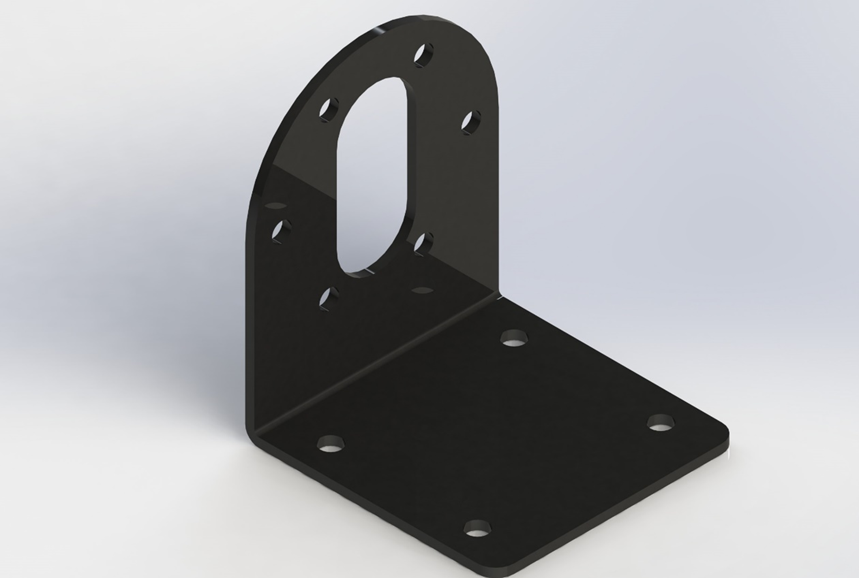
Fabrication of DC Motor Mounting Bracket
Machines Booking Time: 3 Hrs
Max CMF Points Earned: 300 Points
Facility to Book: Fabrication Workbench in Fabrication Lab

Safety Precautions
- Do not use a file without a handle.
- Do not use punches and hammers with a mushroom head.
- Keep your hands away from moving parts.
- Ensure that the workpiece is clamped in the vice firmly and securely.
- Keep the hand tools and vice clean.
- Always use a brush to remove any chips.
- Tuck in your shirts before starting any operation.
- Remove wristwatches, rings, bracelets, etc., since they can lead to injuries.
- Always wear safety shoes.
Objective: To fabricate a DC motor mounting bracket using a mild steel workpiece
Applications:
- Robotics: Secures DC motors in mobile robots, robotic arms, and servo-driven platforms.
- CNC and 3D Printers: Help in mounting stepper/DC motors that drive axes or extruders.
- Agricultural Tools: Fixes motor drives in small-scale seed sowers, sprayers, or hydroponic setups.
Download file
Material Specifications:
Mild steel metal sheets of dimension 300 mm x 250 mm x 2 mm.
Tools Required:
High-speed steel (HSS) drill bits
Manual Bending Machine
Process Sheet
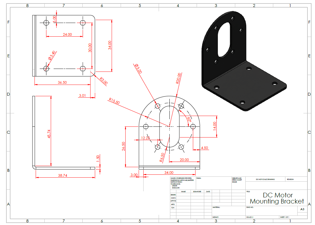
Step 1: Marking of required dimensions
Mark the dimensions of the base plate (50*50 mm), arm (86*40 mm) on the workpiece material using a steel rule, scriber, and try square.
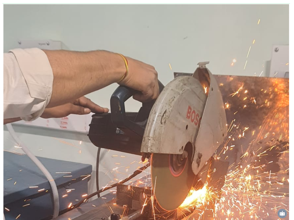
Step 2: Cutting of the required parts
Cut all the parts of the base plate and arm to the required dimensions using a power cutter.
Step 3: File the edges of the workpiece
File the edges of the obtained workpiece using a smooth cut hand file.
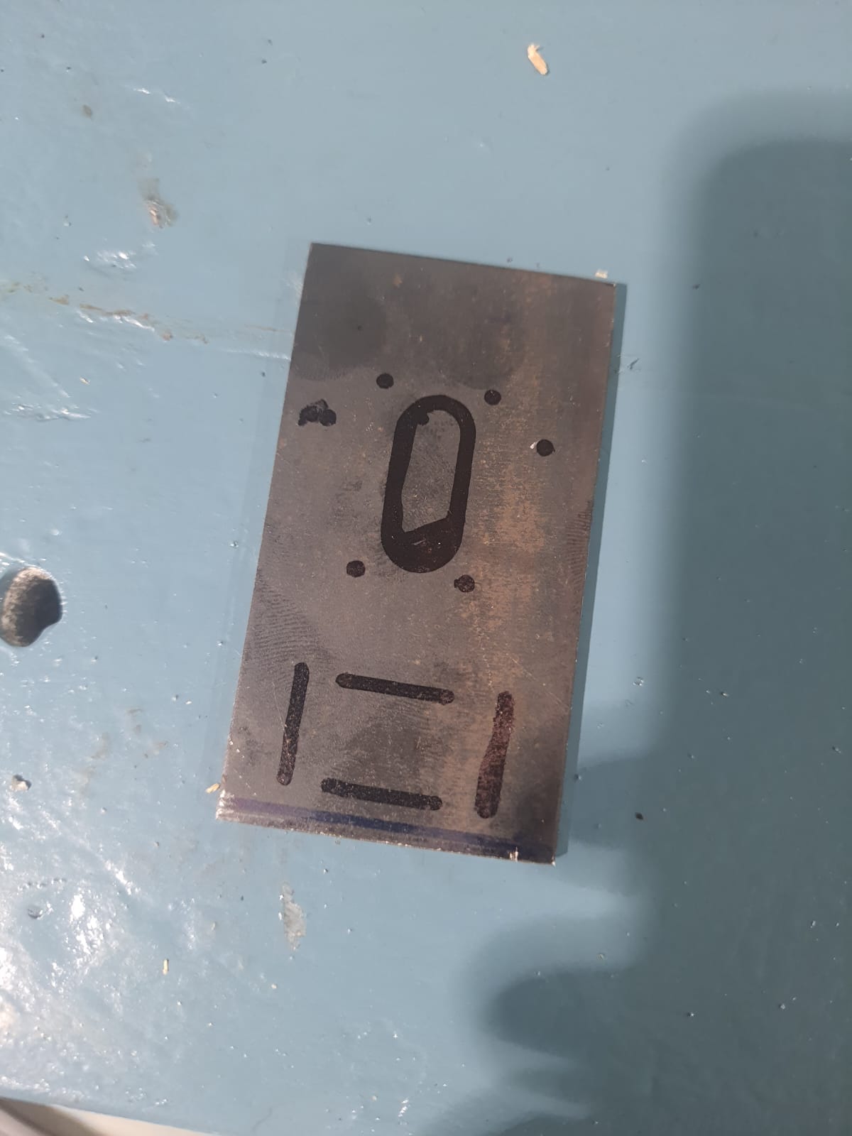
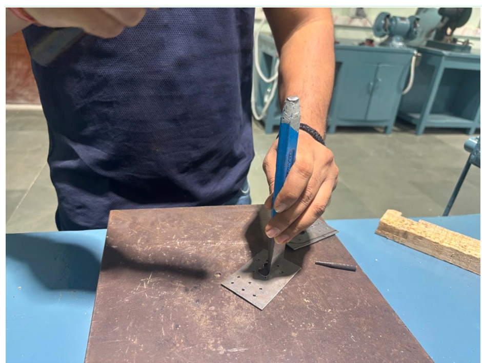
Step 4: Marking of hole positions on the workpiece
Punch all the marked hole positions on the workpiece using the center punch tool and ball peen hammer.
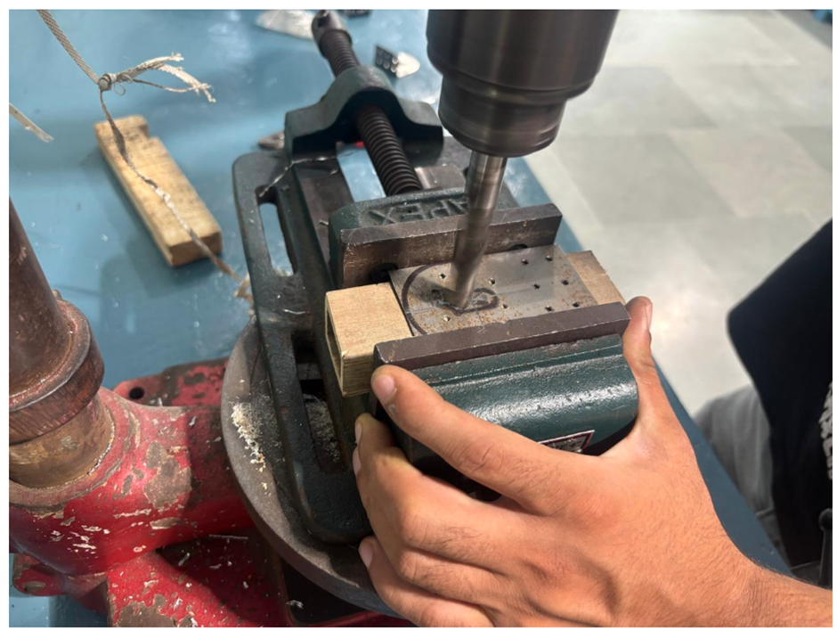
Step 5 : Drill holes for making slot
Drill hole of ø13 mm on top portion of the workpiece for making the slot of 13 mm length using a Radial drill machine with the HSS drill bit of ø13 mm.
Cut out the small section in the middle using a chisel and hammer.
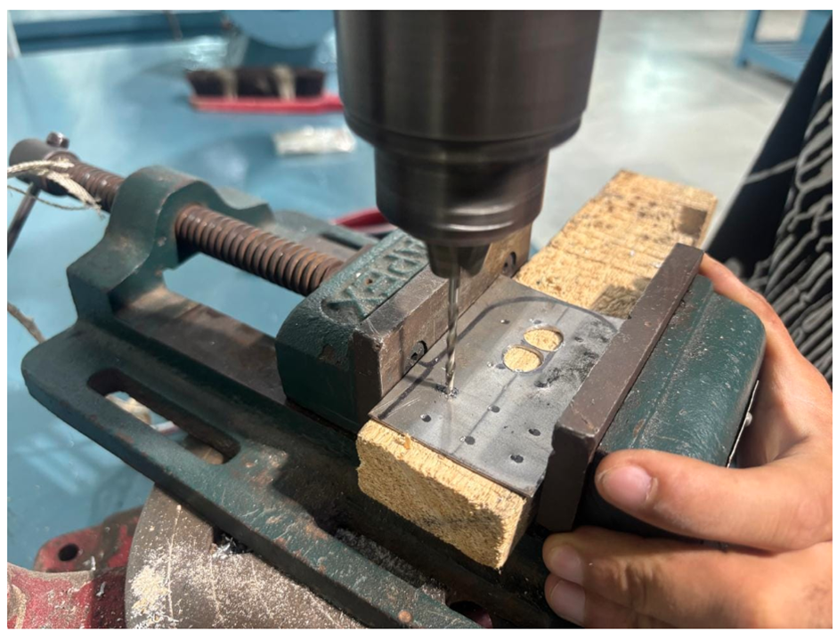
Step 6: Drill holes of the required dimensions on the vertical and horizontal parts of the arm
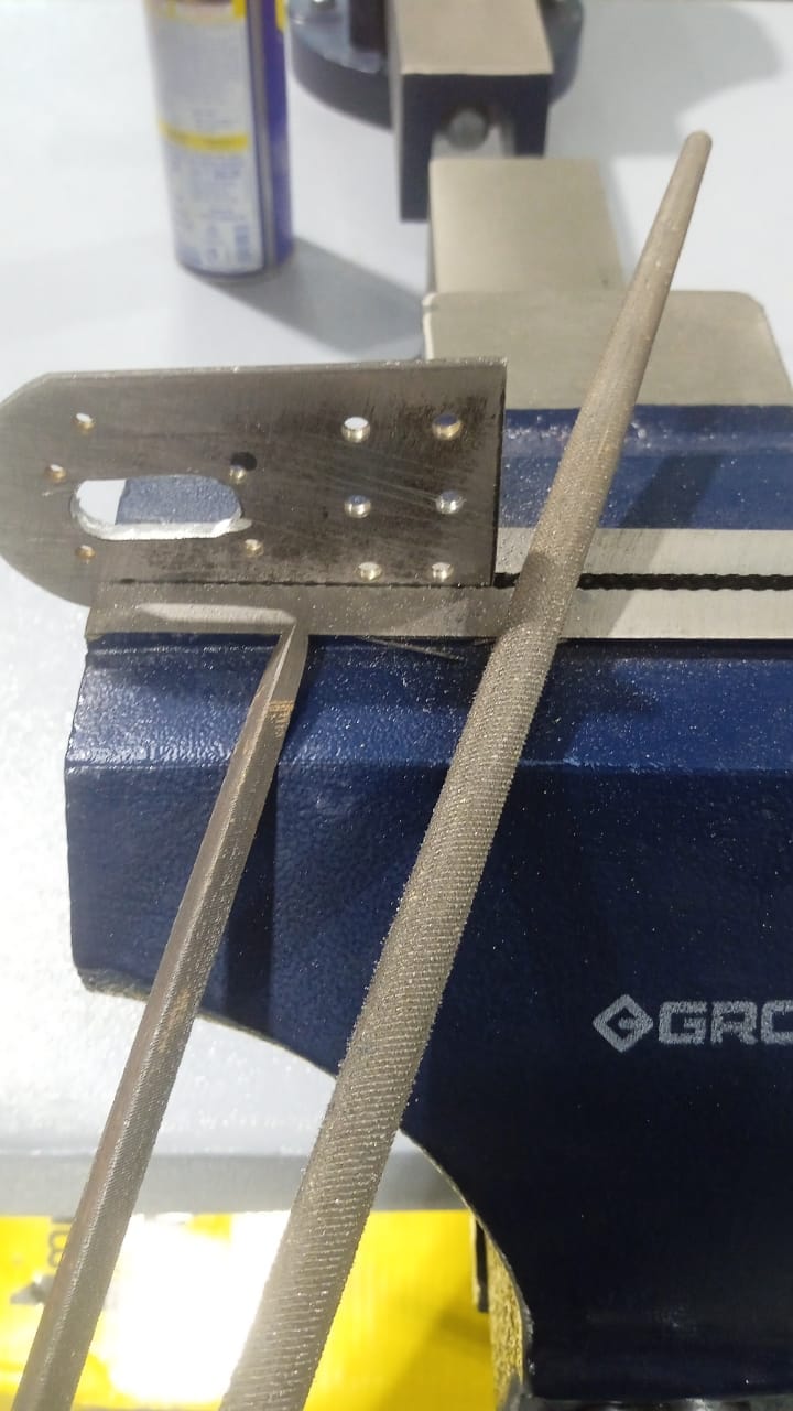
Drill holes of ø3 mm and ø4 mm on the vertical part and horizontal part of the arm using a Radial drill machine with the HSS drill bit of ø3 mm and ø4 mm.
File the drill hole surfaces to remove the burrs using round file.
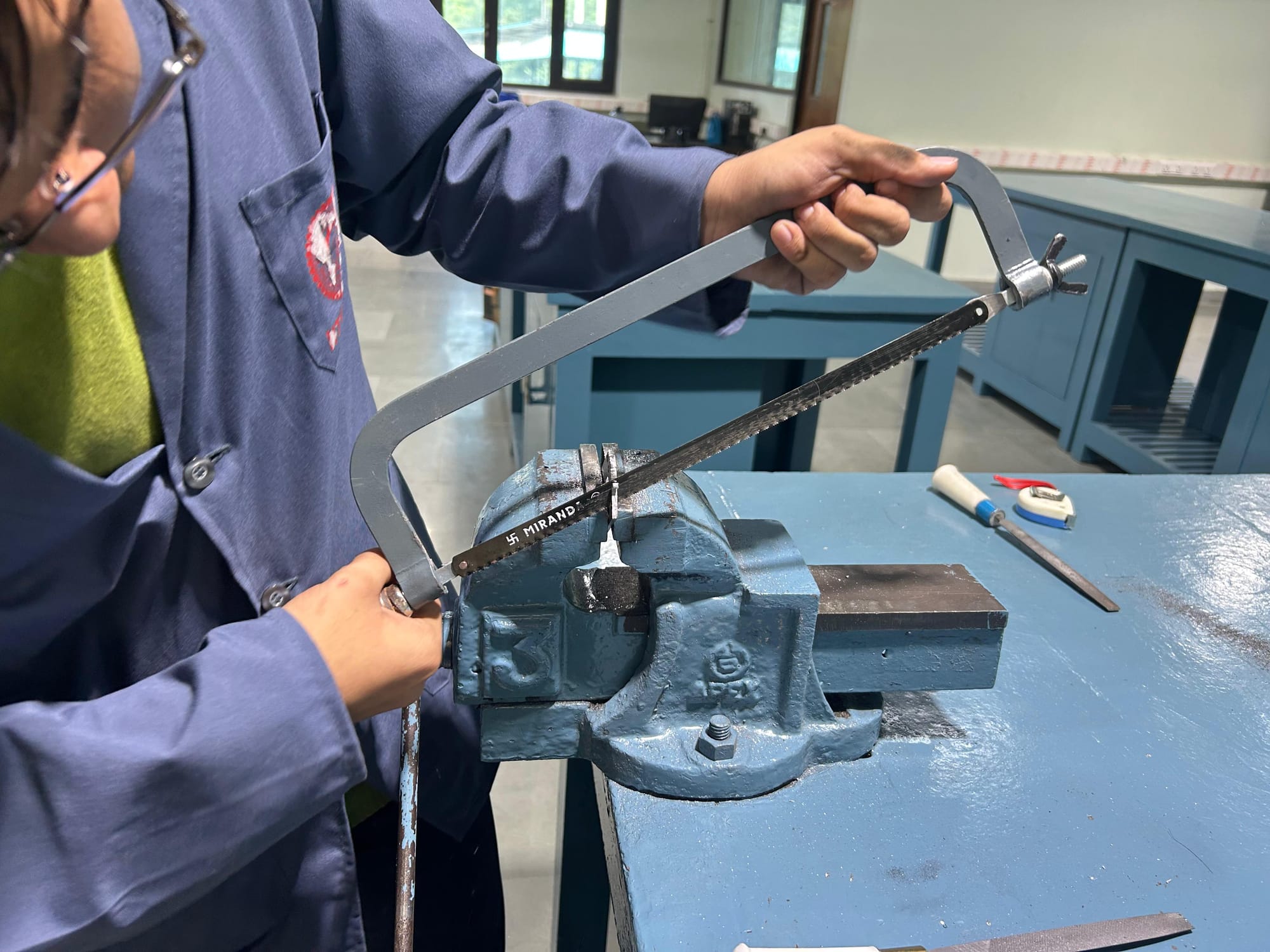
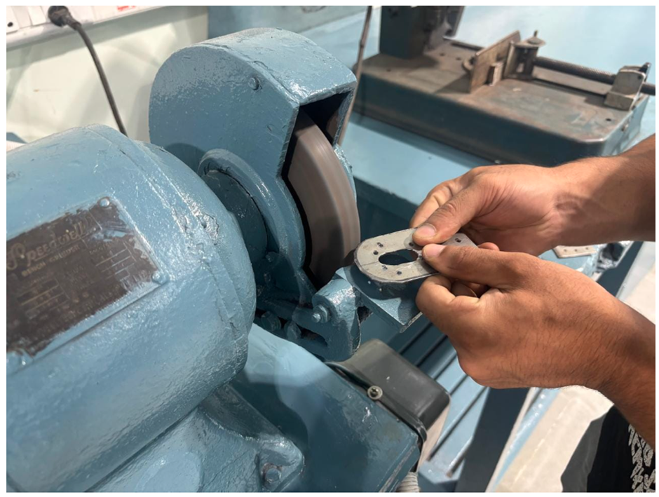
Step 7: Preparation of circular arc on the vertical portion of arm
Make a circular arc of ø40 mm on the top of the vertical part of the arm and file the edge using a Hacksaw and Bench grinder.
Step 8: Filing of inner edges and round edges of workpiece
File the inner edges of the workpiece using a smooth-cut hand file and round areas with a round file to meet the dimensions of the end product.
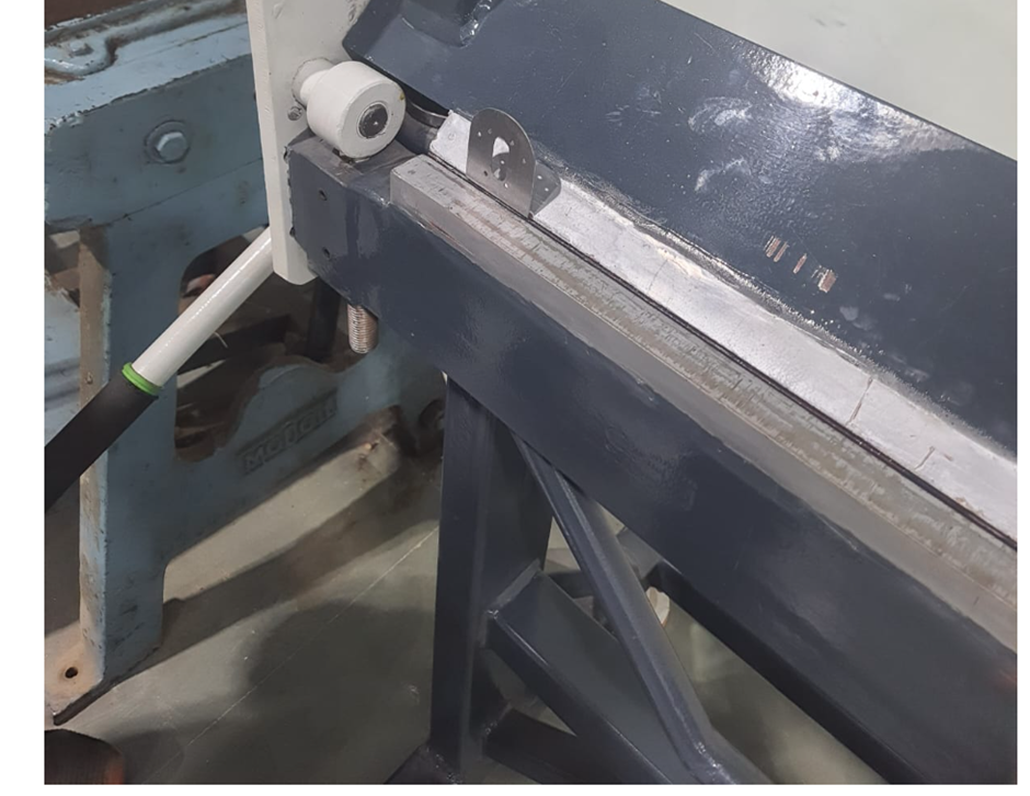
Step 9: Bending of the prepared workpiece to the required dimensions
Mark 40 mm from the base of the plate and bend it at an angle of 90° using Manual bending machine and measure its perpendicularity using a try square.
Step 10: Generation of internal threads inside the machined holes
Make the internal threads of the required dimensions for M3 and M4 screws in drilled holes using tapered, intermediate, and bottoming taps.
Step 11: Fixing the vertical arm to the base plate
Fix the vertical arm to the base plate using screws, nuts, washers, and screw drivers.
Step 12: Testing of the dummy DC motor in the prepared bracket
Insert the dummy DC motor into the prepared bracket hole and tighten all components using screws, nuts, washers, and screw drivers.
Learning Outcomes
Reading and Interpreting Engineering Drawings
Sheet Bending
Mastery of basic hand tools: Files, hacksaws, ball pein hammer, scriber etc.
Understanding of workplace safety practices, tool maintenance, and protective gear usage.