Circuit Simulation using TinkerCAD
Duration: 1 Hr
Training Points: 100
Facility to Book: Workstation
TinkerCAD is a free web app for 3D design, electronics, and coding. We’re the ideal introduction to Autodesk, a global leader in design and make technology.
- Click on "Students Account"
- Sign In with "Google Account"
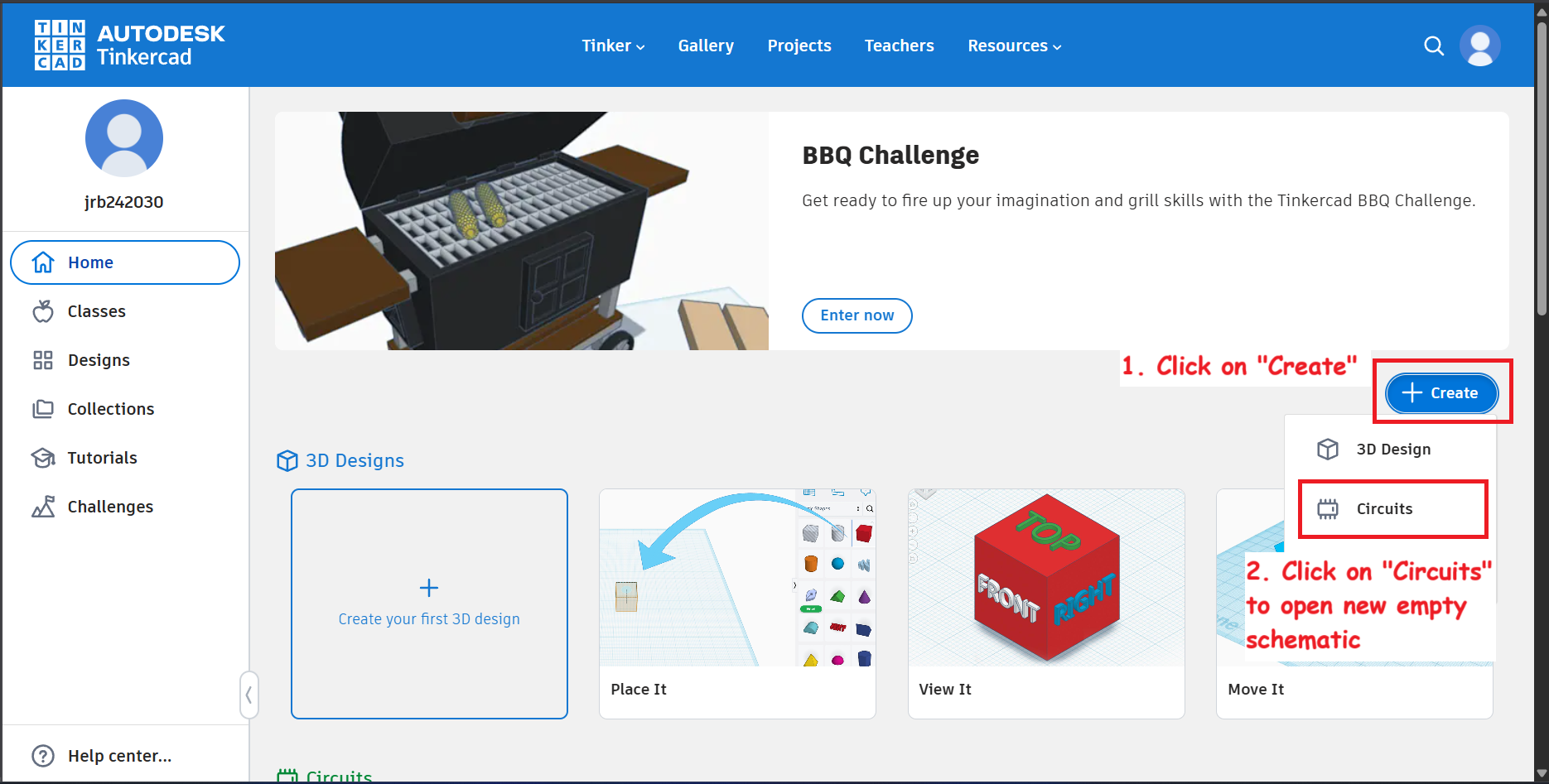
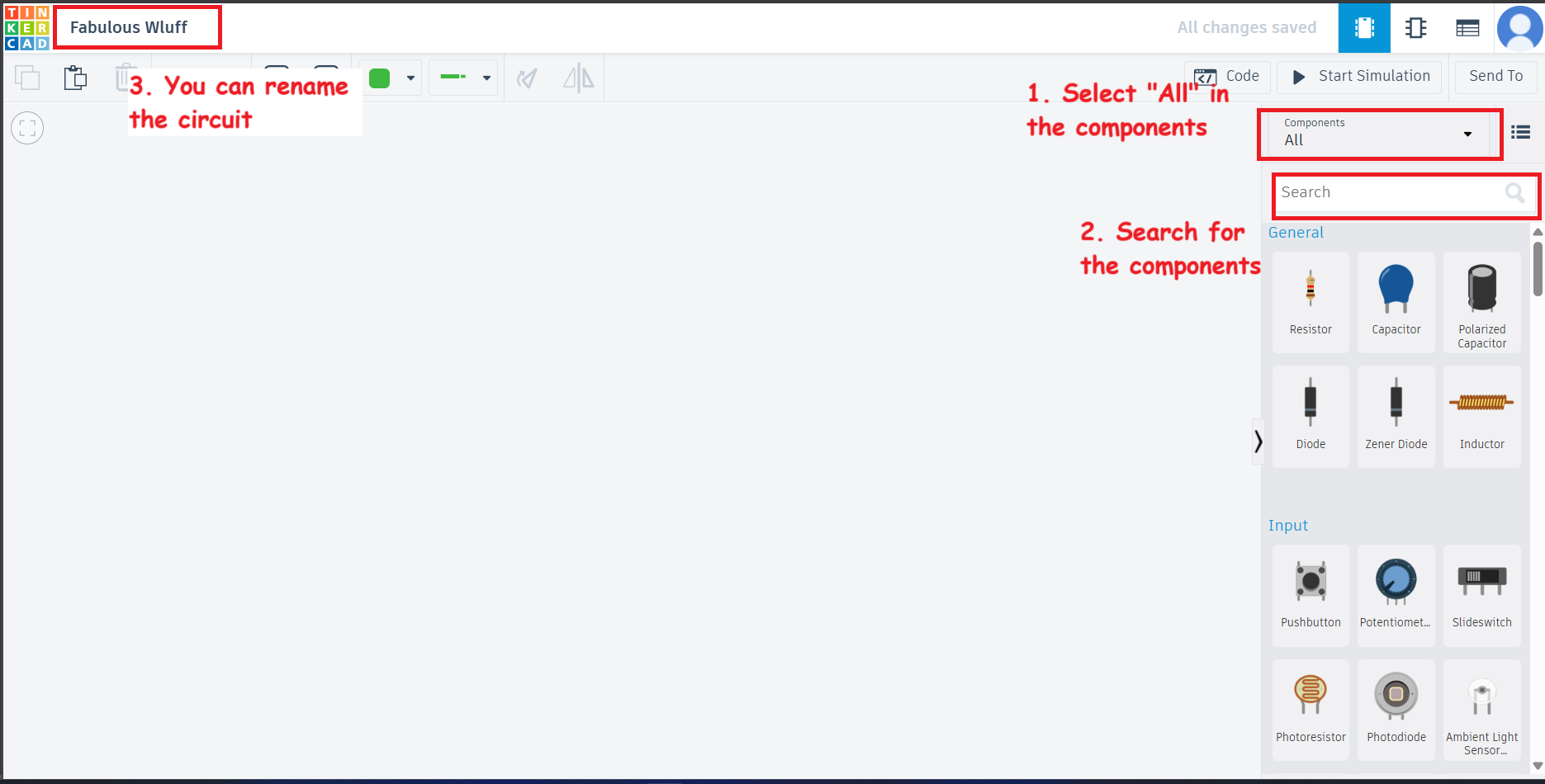
- Create new empty "Circuit"
Task 1.
- Blink an LED {Prewritten Code from TinkerCAD}
- Add a pushbutton to it.
Objectives :
- Familiarity with Arduino Uno
- Familiarity with LED - A Polar device
- Creating circuit
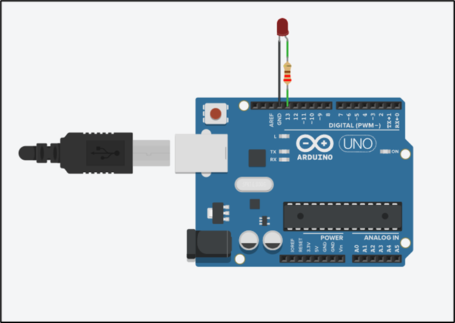
Circuit Diagram :
- Blink an LED
- Add an push button to the circuit
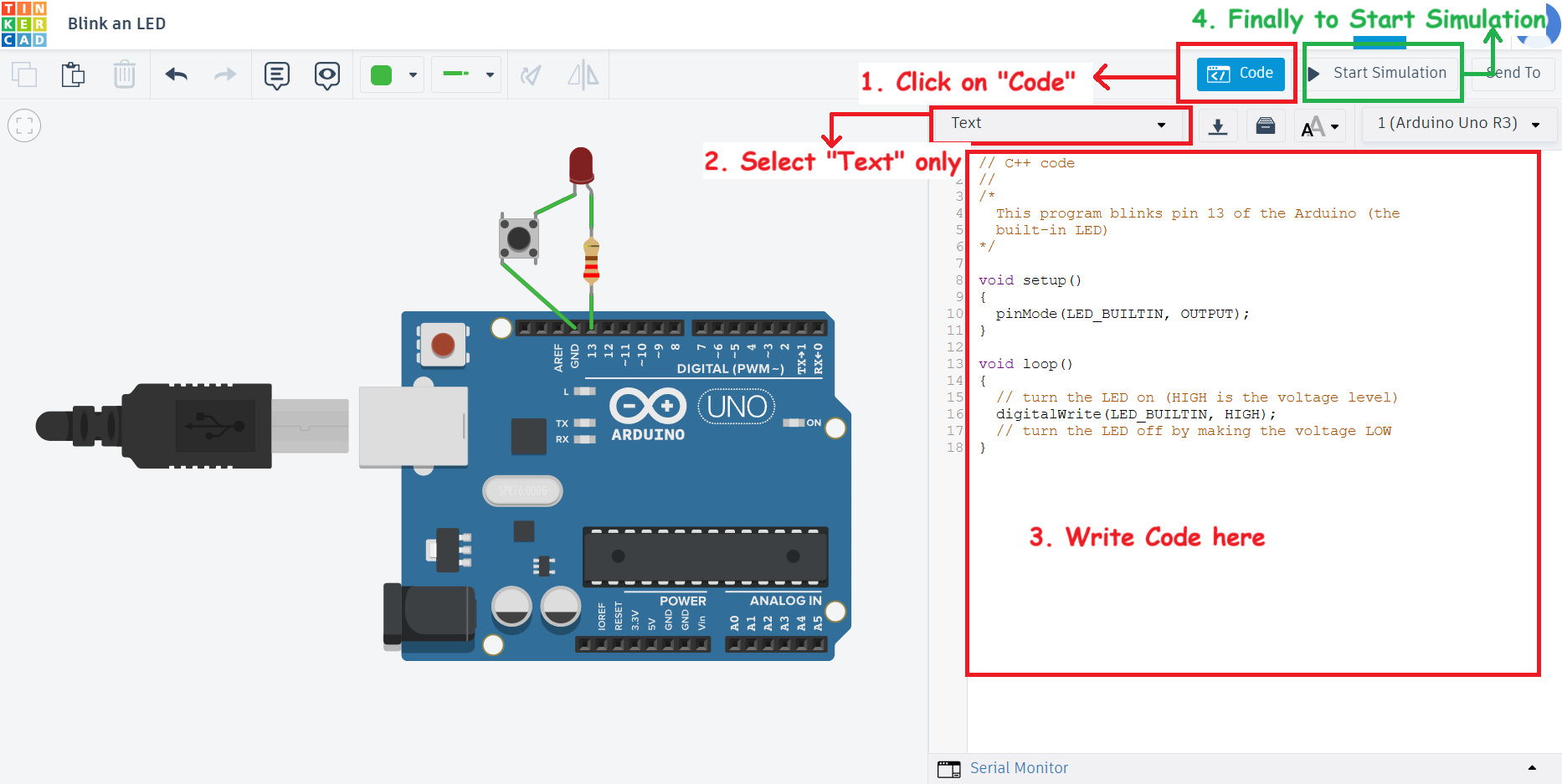
Coding Arduino:
In Arduino, the main function is managed by the framework, and you typically do not need to write main() yourself. Instead, you write the setup() and loop() functions, which the Arduino runtime uses internally in its main() function like this (behind the scenes):
// C++ code
//
/*
  This program blinks pin 13 of the Arduino (the
  built-in LED)
*/

void setup()
{
  pinMode(LED_BUILTIN, OUTPUT);
}

void loop()
{
  // turn the LED on (HIGH is the voltage level)
  digitalWrite(LED_BUILTIN, HIGH);
  // turn the LED off by making the voltage LOW
}
Task 2. Seven Segment Display
Objectives :
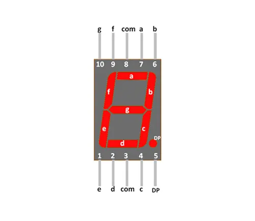
- Types of 7 Segment display (CA {Common Anode} and CC {Common Cathode})
- Connections in Bread board
- Familiarity with 7 Segment Display
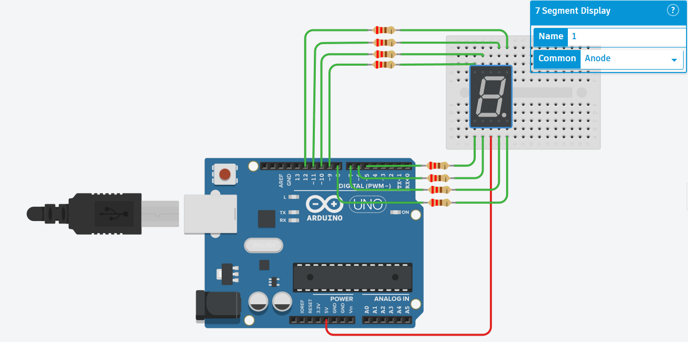
Circuit Diagram :
Coding Arduino:
// Counter initialized with maximum integer = 9
// For a 7 Segment
int counter = 9;
// Declaring constant integers
// For connection with each Arduino pins
const int A = 11;
const int B = 12;
const int C = 7;
const int D = 6;
const int E = 5;
const int F = 10;
const int G = 9;
const int DP = 8;// Setting up the roles of pins
// i.e. Output
void setup()
{
pinMode(A, OUTPUT);
pinMode(B, OUTPUT);
pinMode(C, OUTPUT);
pinMode(D, OUTPUT);
pinMode(E, OUTPUT);
pinMode(F, OUTPUT);
pinMode(G, OUTPUT);
pinMode(DP, OUTPUT);
}void loop()
{
// Display function to call
// which we will write in next block and which will take care
// of displaying on 7-segment
display(counter);
// Decrease counter
counter -= 1;
if (counter == -1)
{
counter = 9;
}
// Add Delay for 1 sec
delay(1000);
}void display(int count)
{
int a = 1;
int b = 1;
int c = 1;
int d = 1;
int e = 1;
int f = 1;
int g = 1;
int dp = 1;
switch (count)
{
case 1:
b = c = 0;
break;
case 2:
a = b = d = e = g = 0;
break;
case 3:
a = b = c = d = g = 0;
break;
case 4:
b = c = f = g = 0;
break;
case 5:
a = c = d = f = g = 0;
break;
case 6:
a = c = d = e = f = g = 0;
break;
case 7:
a = b = c = 0;
break;
case 8:
a = b = c = d = e = f = g = 0;
break;
case 9:
a = b = c = d = f = g = 0;
break;
default:
count = 0;
a = b = c = d = e = f = 0;
break;
}
// Writing output pins with its Corresponding HIGH or LOW values
// via variables a, b, c, etc.
digitalWrite(A, a);
digitalWrite(B, b);
digitalWrite(C, c);
digitalWrite(D, d);
digitalWrite(E, e);
digitalWrite(F, f);
digitalWrite(G, g);
digitalWrite(DP, dp); // Keep DP off; set to 1 if you want the dot on
}You might have read 1 implies HIGH signal, then why are we assigning 0 which is LOW in this case and still able to glow the respective LEDs 🤔 ?
The answer lies in our circuit diagram. 😀
Our Configuration is common anode. We know that across a diode we need a voltage difference so that current will flow through it. Since we have common anode that is we are giving a HIGH always at one end of LED and now if at the other end we give HIGH then no current will flow across LED and resulting in OFF state of LED. Instead if we give a LOW at other end then quite opposite will happen and LED will glow.
Task 3.
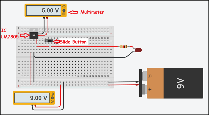
- Voltage Regulator IC LM7805
- Testing using Multimeter
Objectives :
- Familiarity with Multimeter
- Need of voltage Regulation – (Need of constant voltage to some sensors exceeding which can burn them)
Learning Source:
- Introduction to TinkerCAD
- Arduino with TinkerCAD