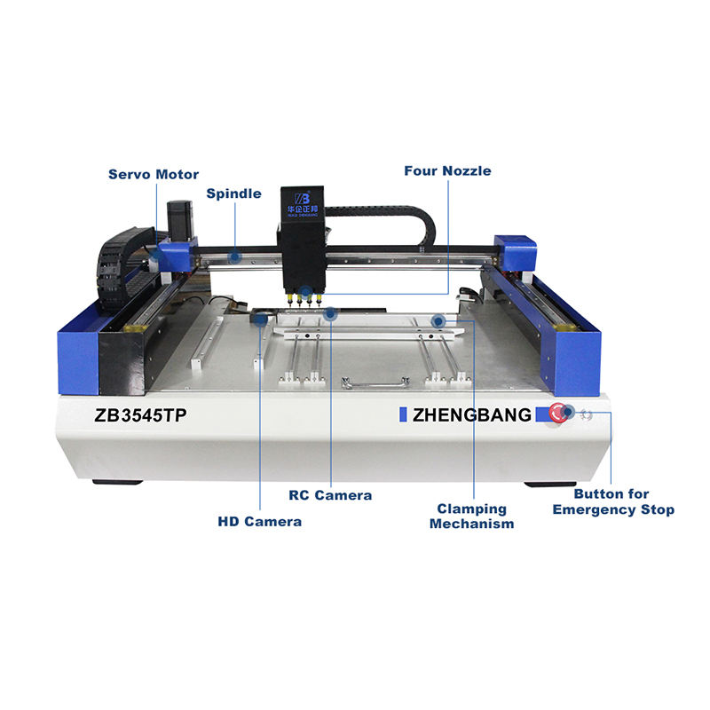
SMT Pick & Place
Duration: 2 Hrs
Training Points: 200
Facility to Book: SMT Pick & Place Machine (Digital Manufacturing Lab)
A pick and place machine is an essential part of modern PCB (printed circuit board) assembly, especially in SMT (surface mount technology) manufacturing. It automates the process of placing surface-mount components onto the board accurately and quickly. The SMT workflow is mentioned below. Steps 2-5 are addressed by the Pick and Place Machine.
- Preparation Stage:
- The PCB is prepared with solder paste on its pads using a stencil printer.
- Components (resistors, capacitors, ICs, etc.) are loaded into feeders, which can be tape reels, tubes, or trays.
- PCB Loading:
- The PCB is fed into the machine via a conveyor belt or manually placed on a vacuum or mechanical fixture.
- Component Pickup:
- The machine has robotic arms or nozzles with vacuum suction.
- A vision system or mechanical positioning ensures the nozzle picks the component from the feeder accurately.
- Alignment and Inspection:
- A camera system checks the component's orientation and adjusts it mid-air if necessary.
- Some high-end machines are equipped with bottom cameras that inspect the component before it is placed.
- Component Placement:
- The nozzle moves to the exact coordinate on the PCB and places the component onto the solder-pasted pad.
- Placement is precise, often within micrometers.
- Reflow Soldering (after pick-and-place):
- The populated PCB is sent to a reflow oven, where solder paste melts and permanently attaches components to pads.
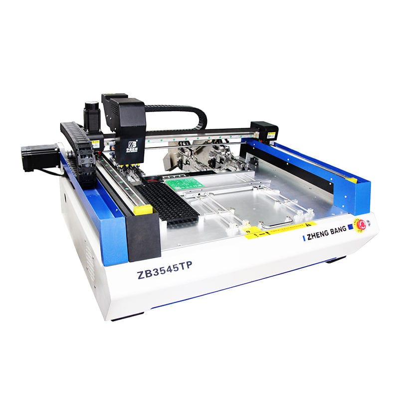
The below-mentioned steps need to be followed in the ZHENG BANG ZB3545TP Pick and Place Machine.
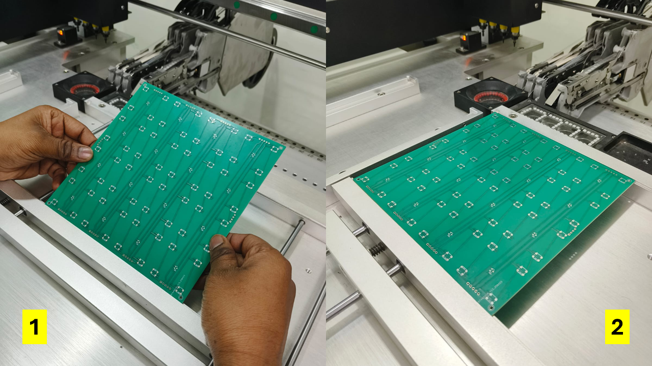
- Place the PCB on the machine bed by adjusting the clamps. The flexible front clamp is pulled towards the body, and the PCB is placed. Then it is moved to the left end of the holding bed.
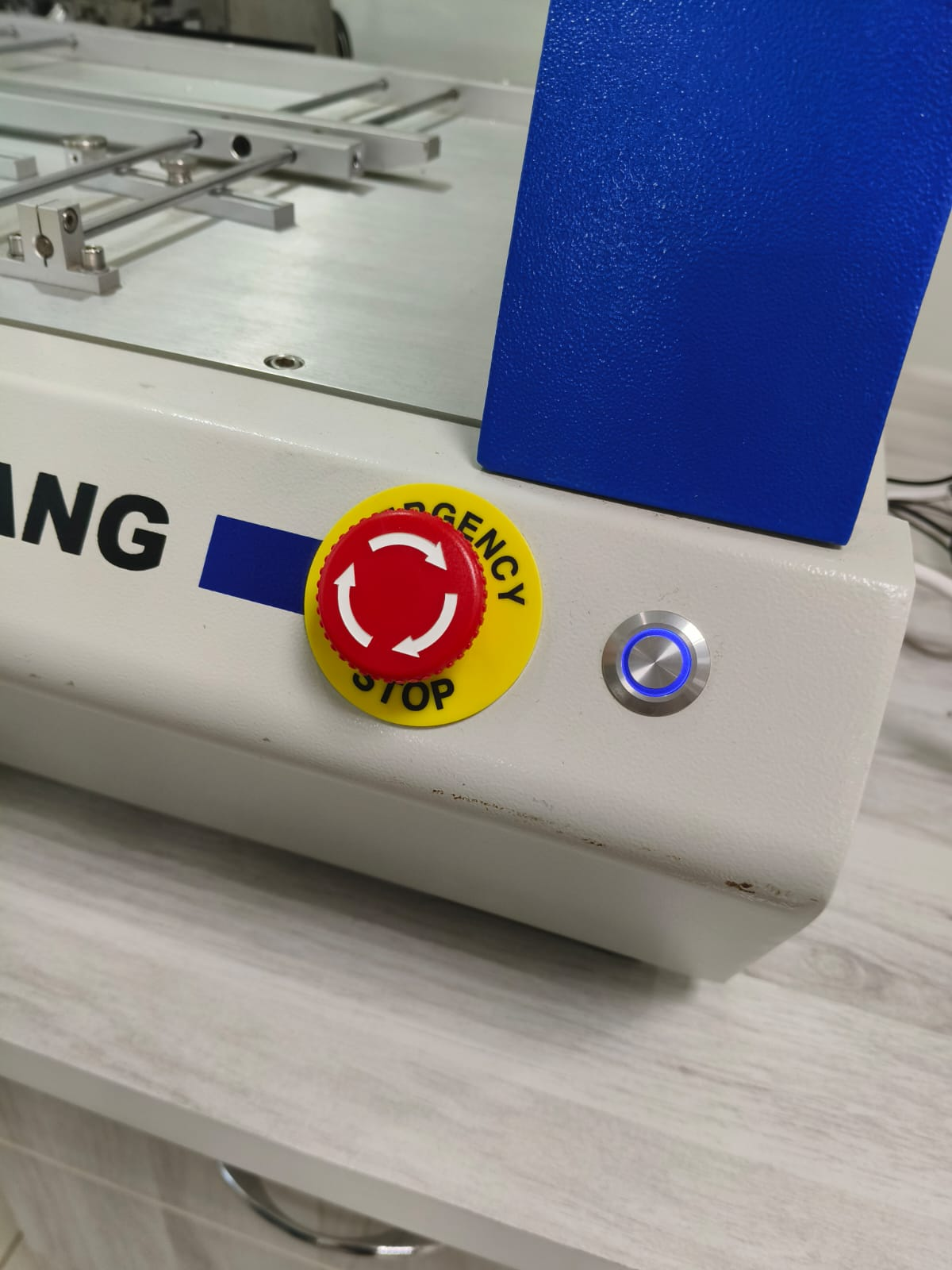
- Turn the power switch on by rotating the power knob at the right side of the machine.
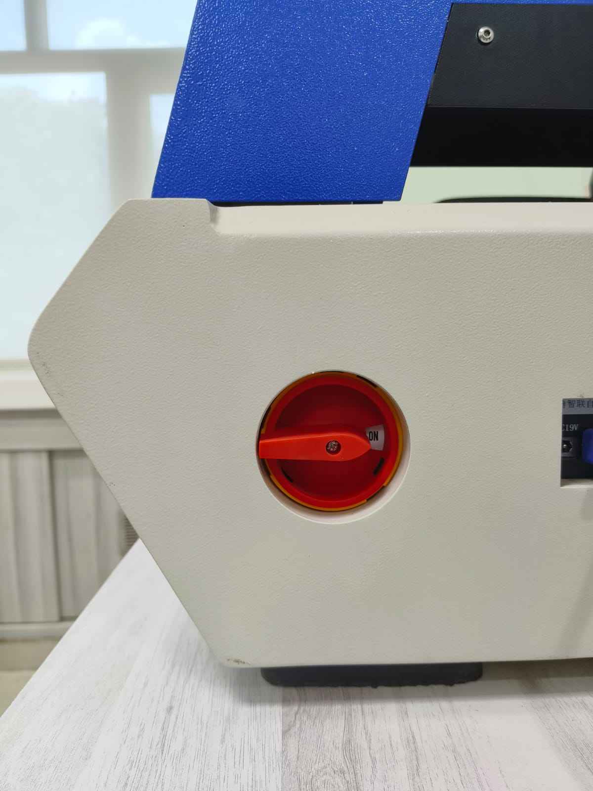
- Rotate the emergency switch clockwise to disengage it. The blue light indicates that the machine is ON.
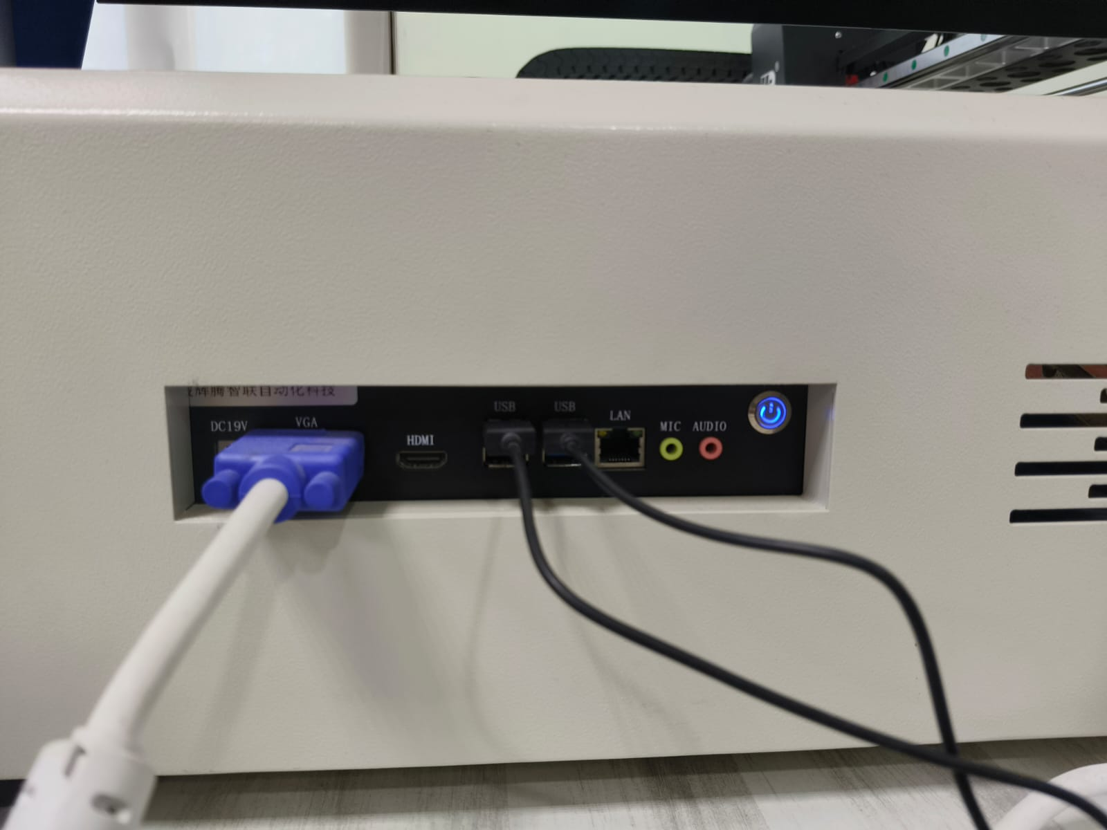
- The side panel is connected to the computer where the machine software is installed. The blue light indicates that the communication between the machine and the computer is ON.
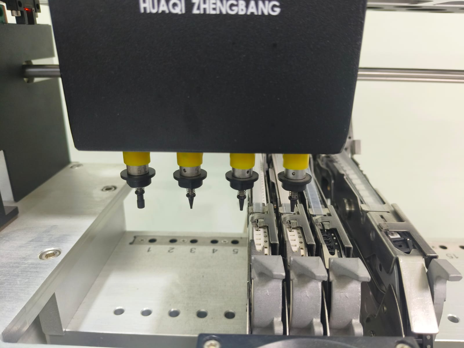
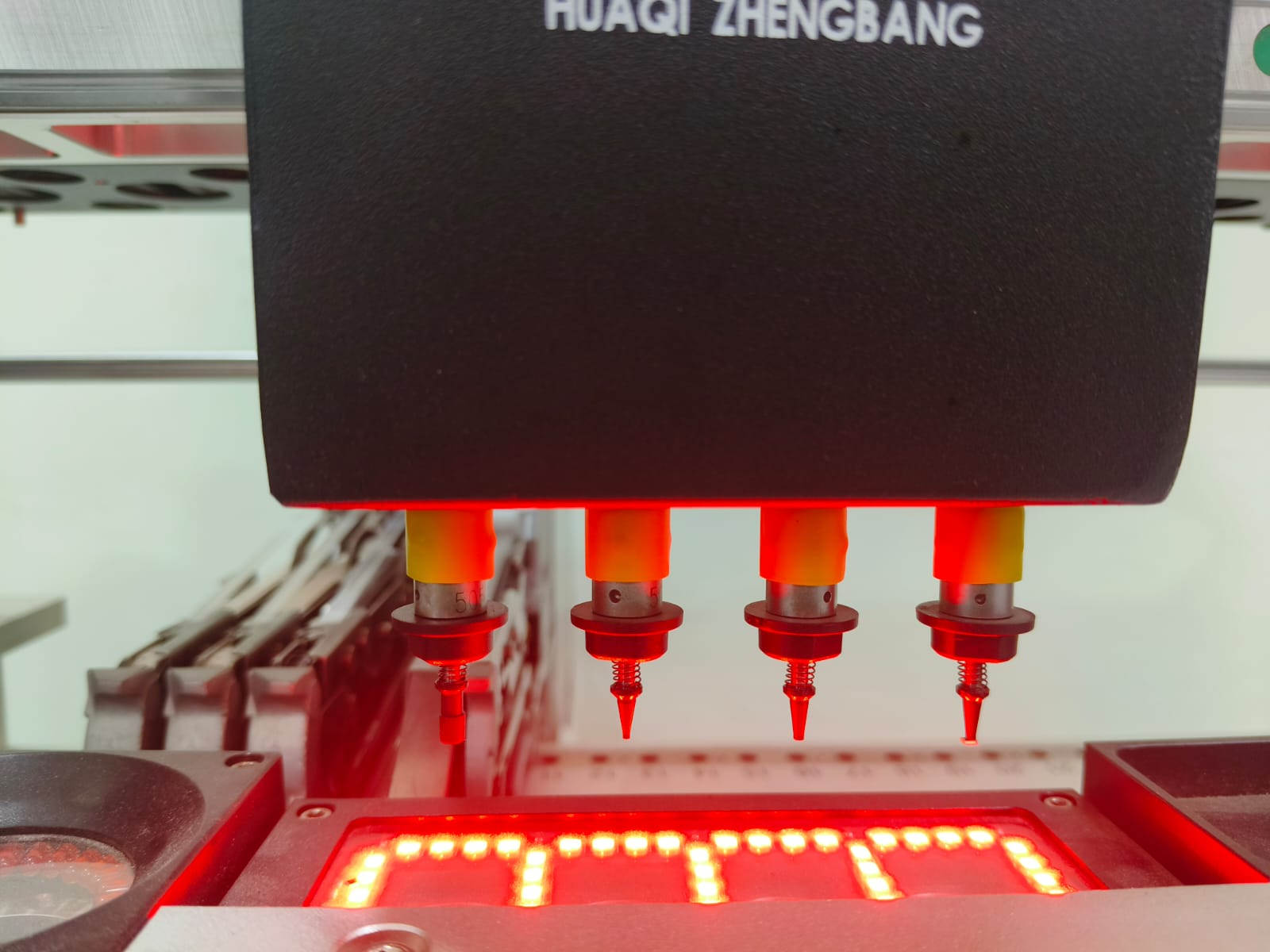
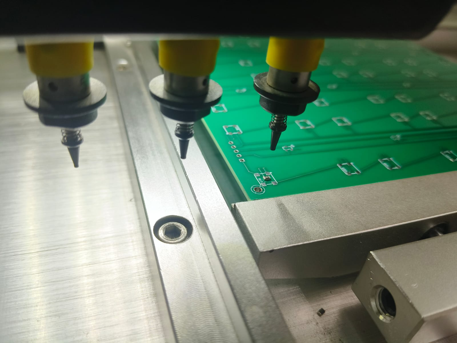
- As soon as the emergency switch is unlocked, the computer will turn on. The nozzles at the default home position looks like
Open the machine software.

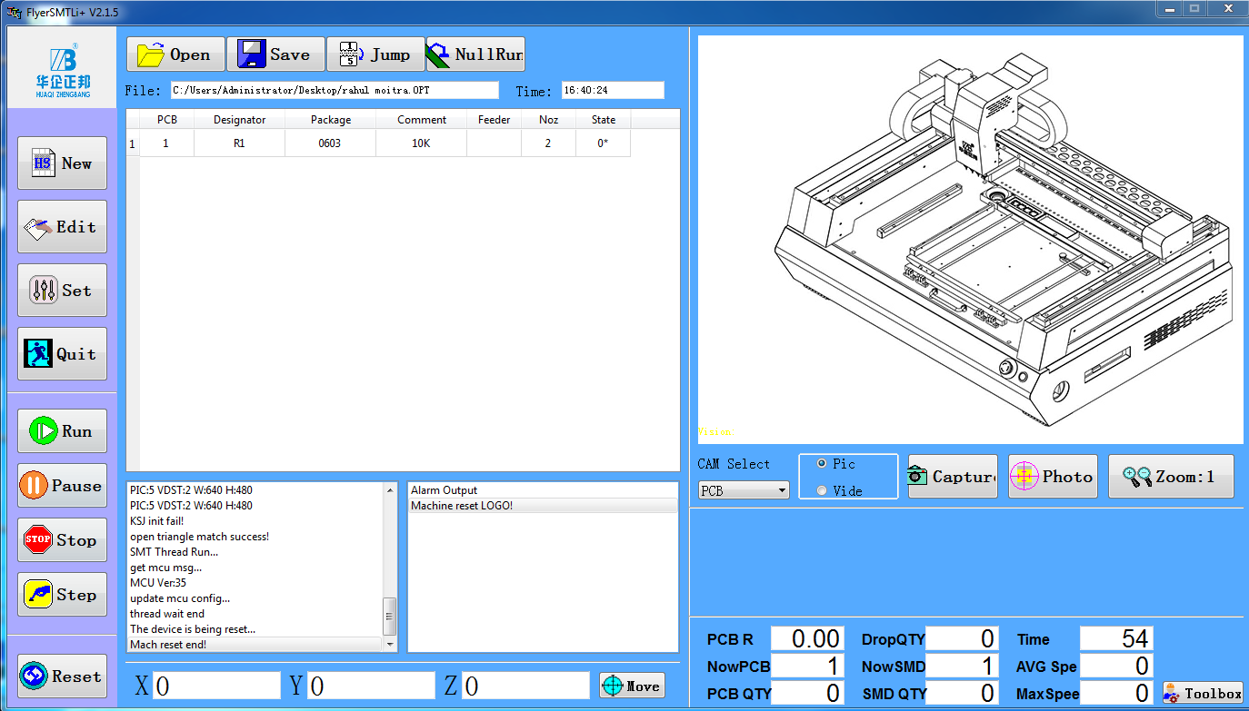
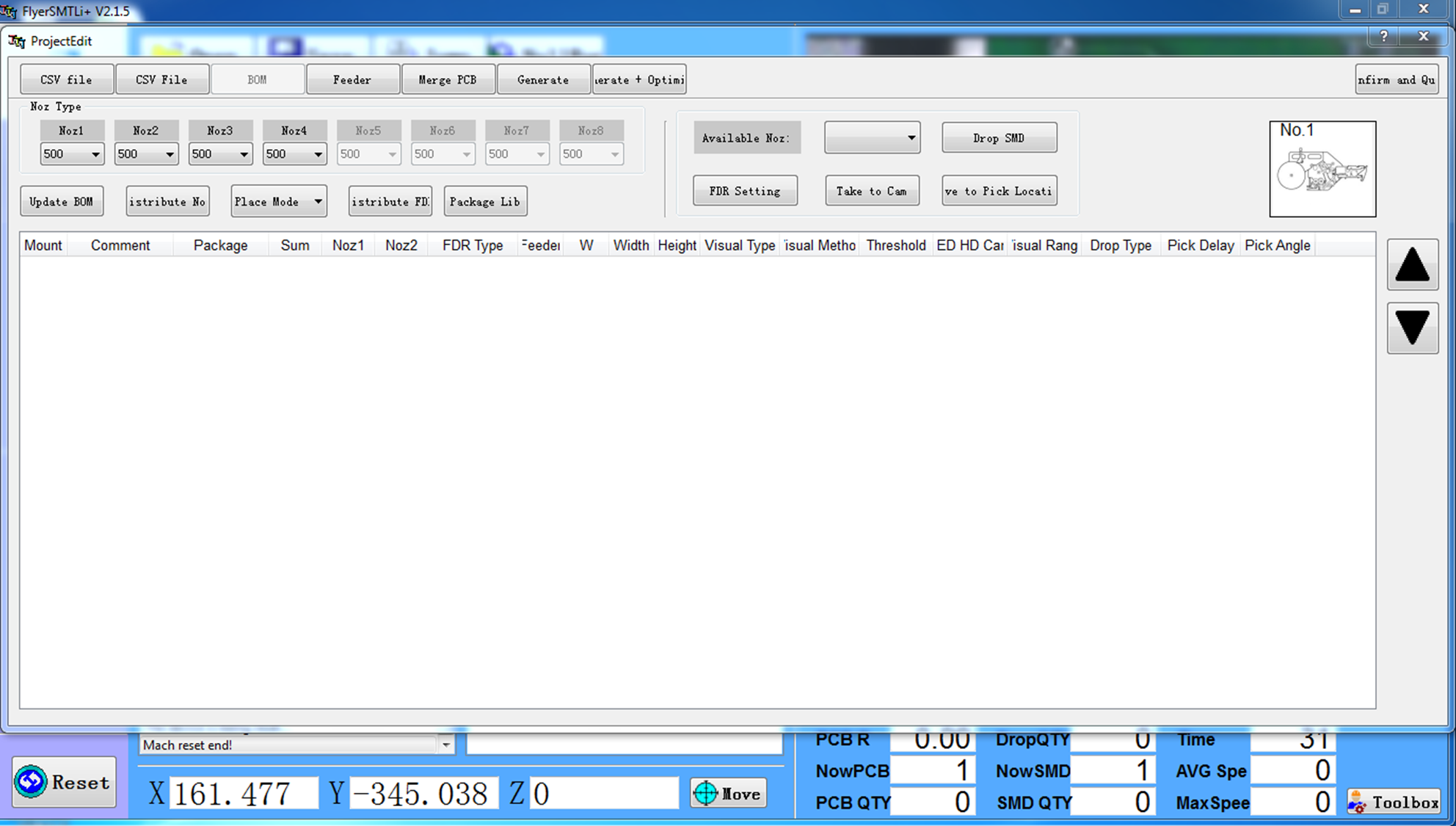
The user interface of the software is displayed as follows.
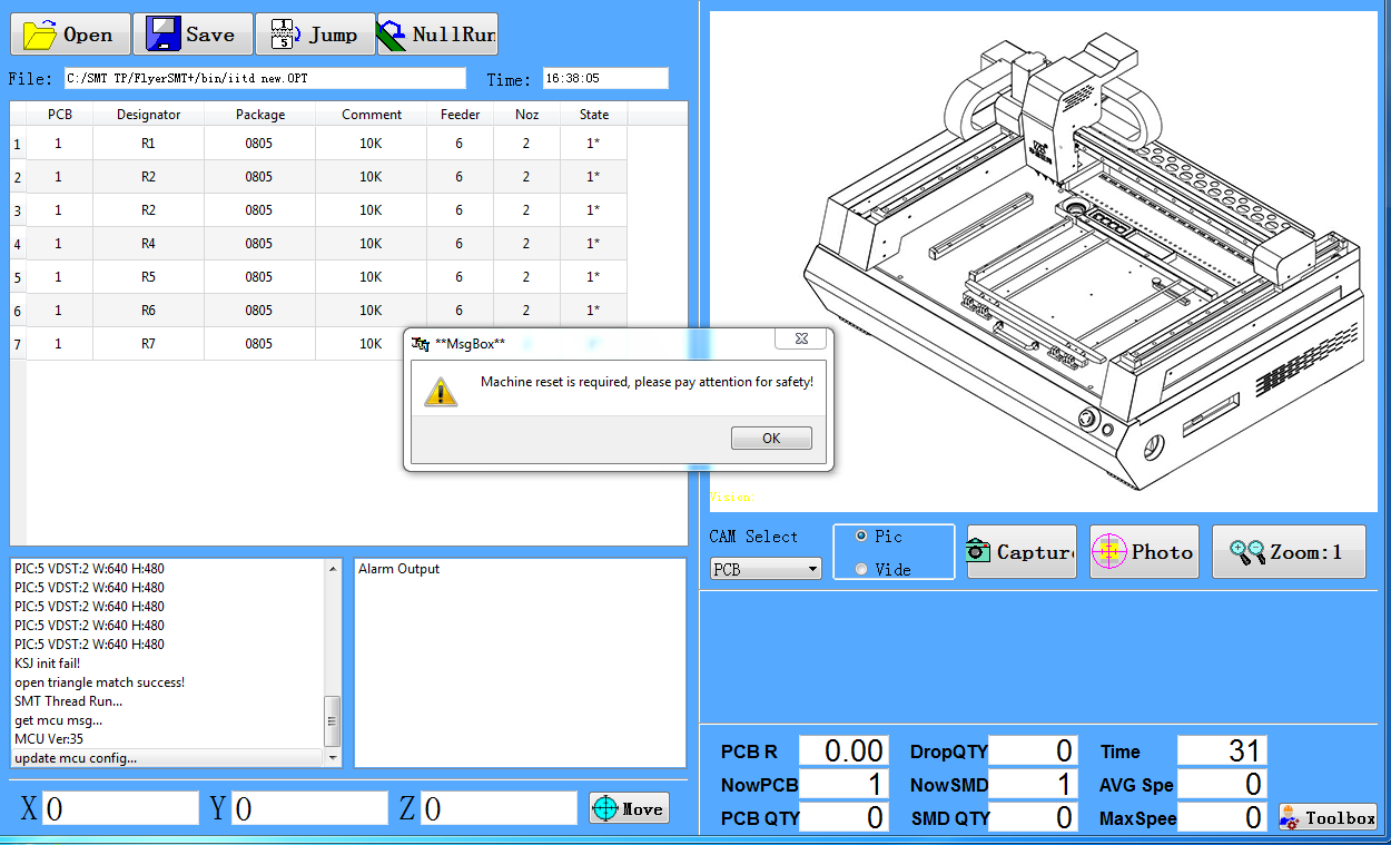
- Click on OK. Then click on New and choose the file location. Name it and save it as an .opt file.
- Click on SET BM1
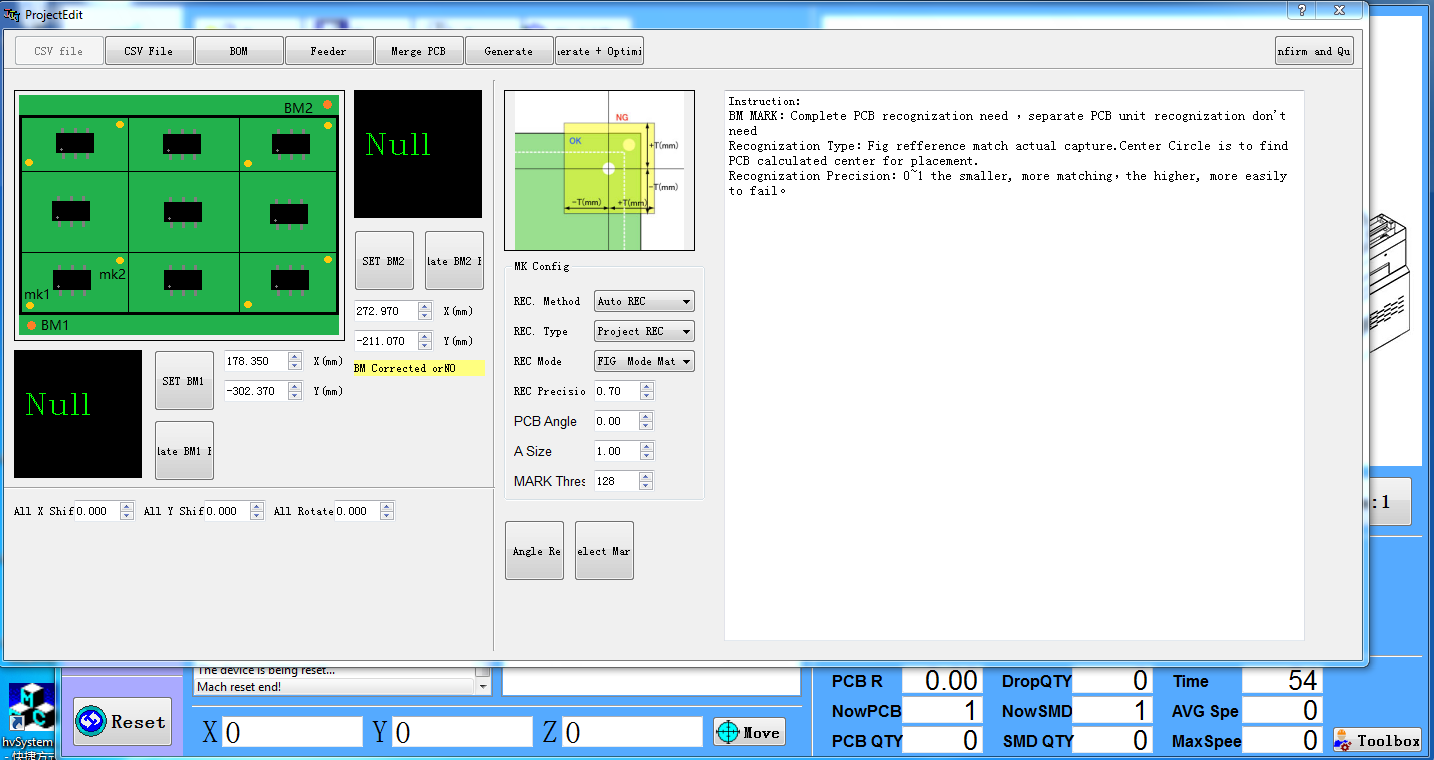
- Click on Location.
- Use the arrow keys on the computer screen to position the tooltip. Then press Confirm.
- Click on SET BM2 and position the tooltip in a similar fashion, and then Confirm. The BM1 and BM2 points should be diagonally placed.
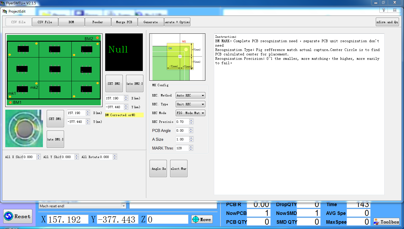
- Click on late BM1 and late BM2 to confirm that the tooltip moves to the specific coordinates of BM1 and BM2.
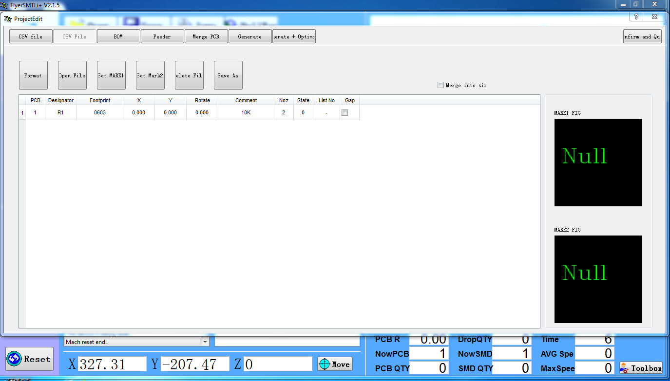
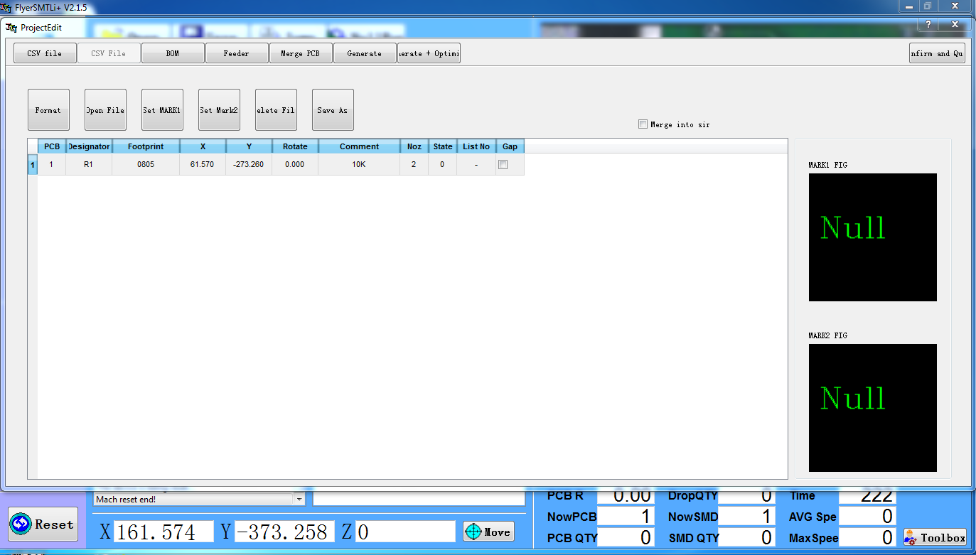
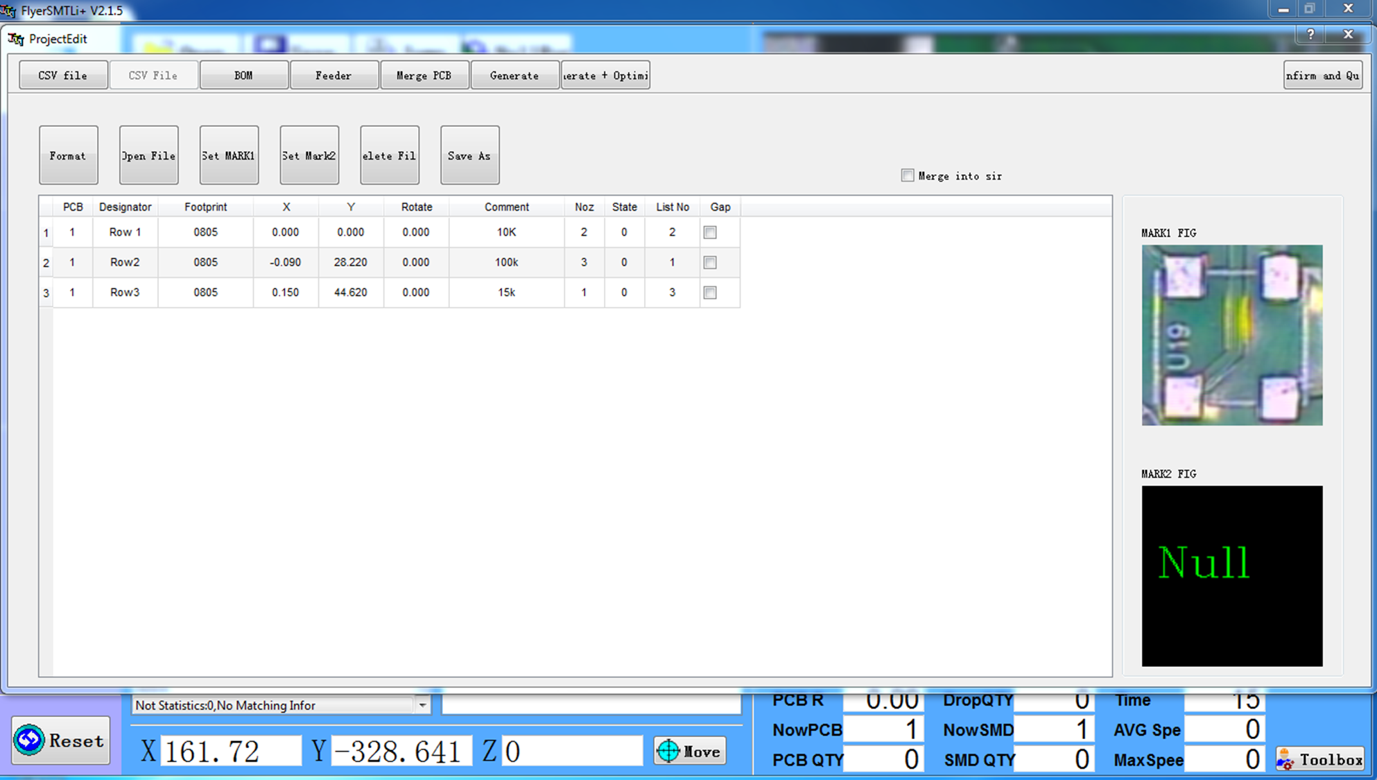
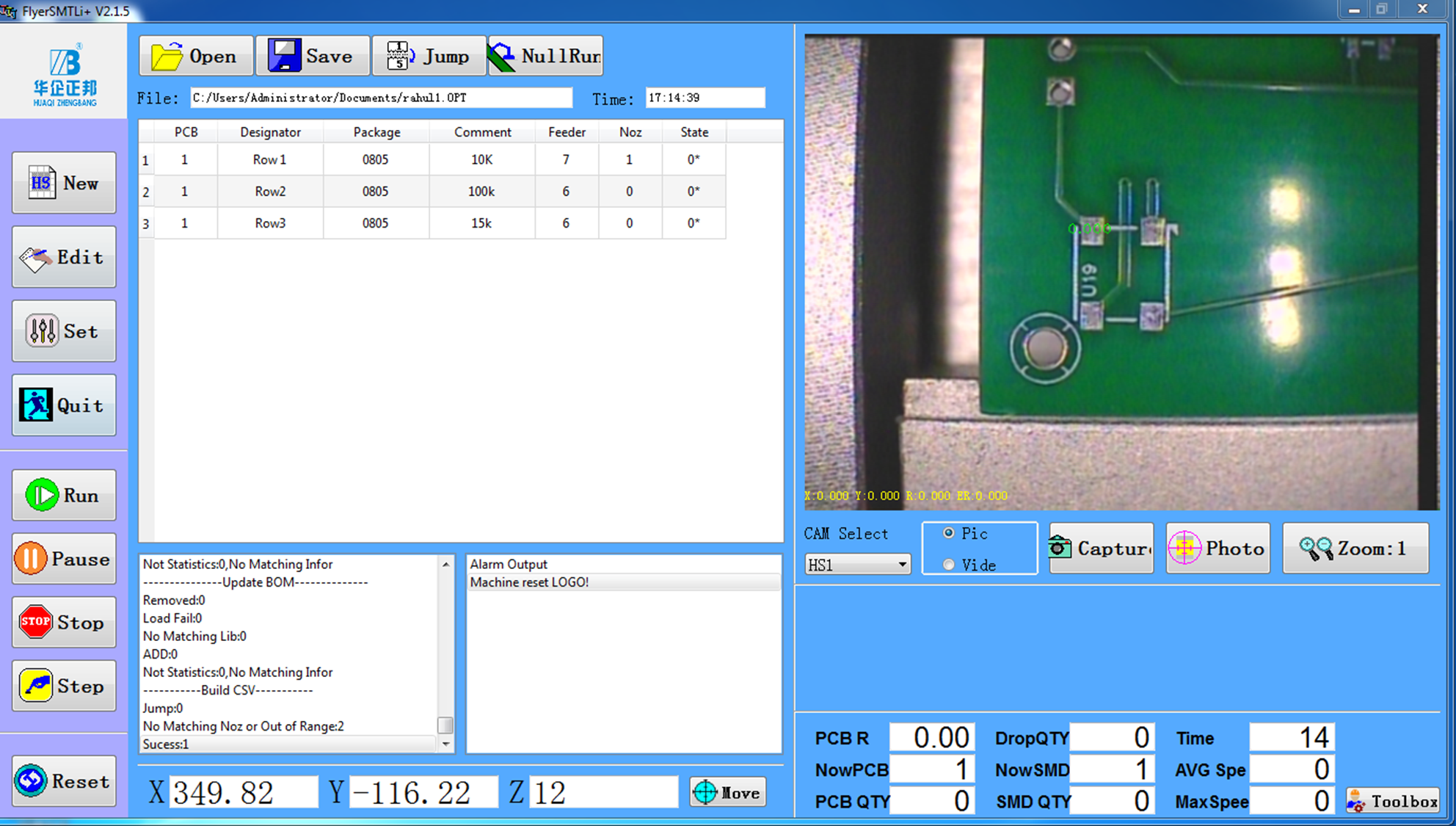
- Click on CSV File. The screen will then appear as
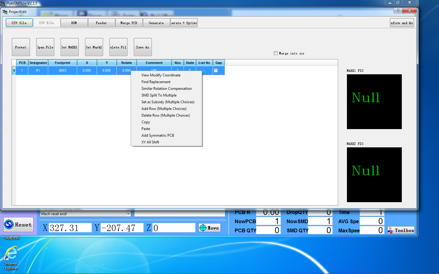
- Right-click on the stored row, then go to View Modify Coordinate.
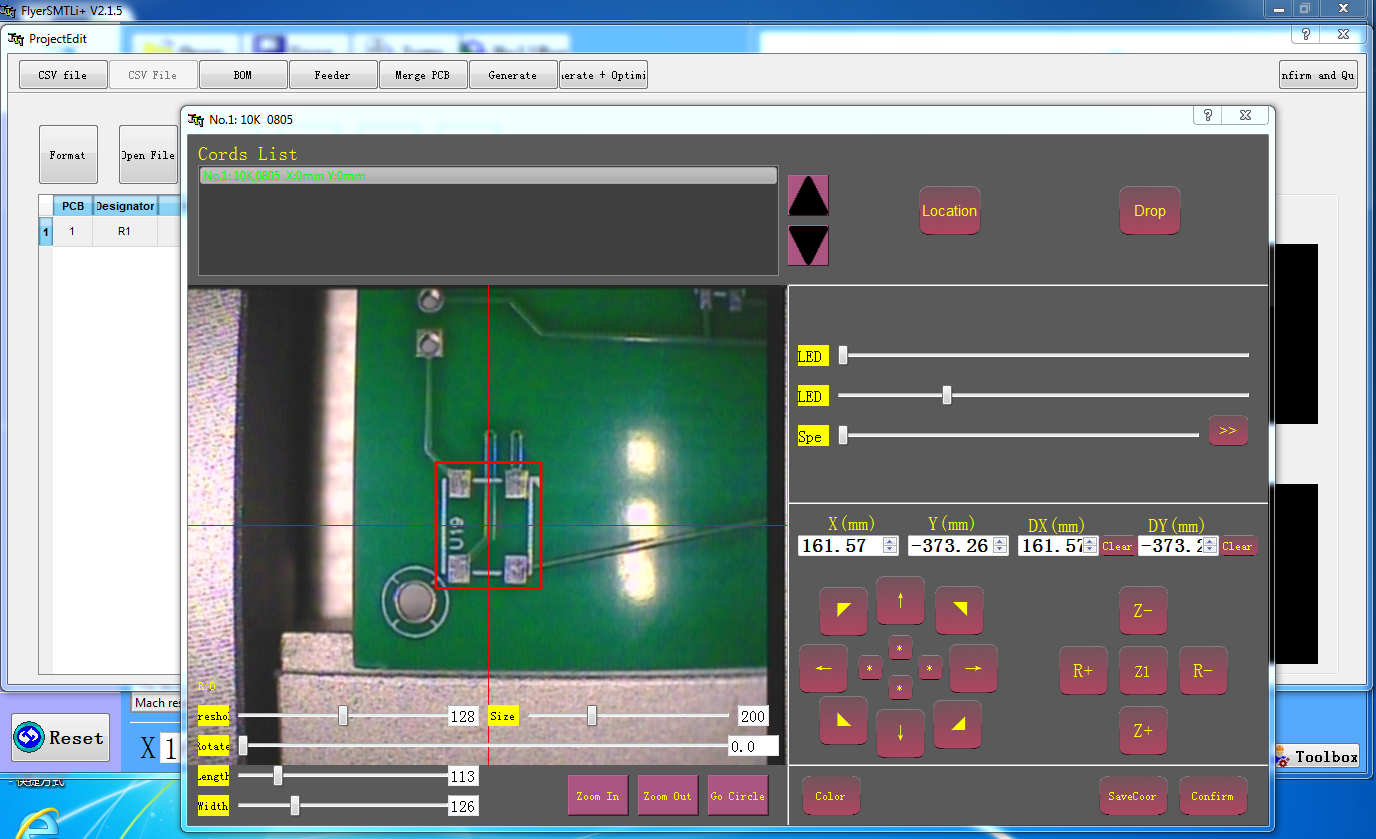
- The coordinates of the PCB components should be set using the arrows on the screen. Then click on Savecoor and Confirm.
- The coordinates can be seen as follows.
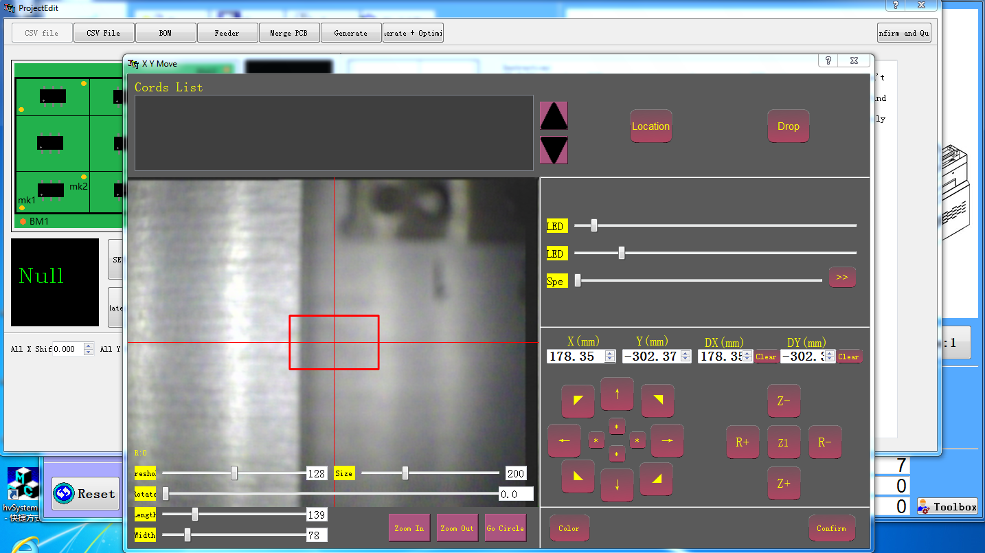
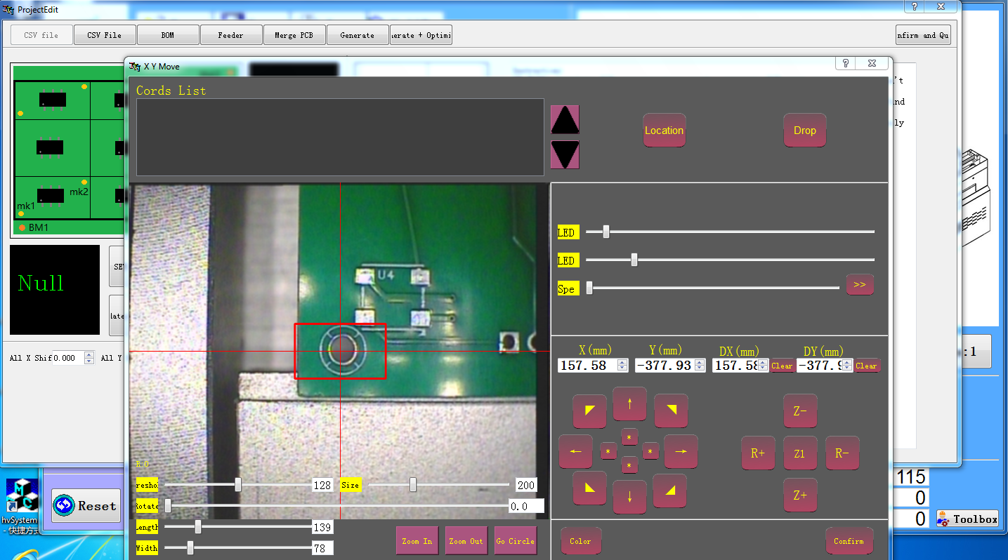
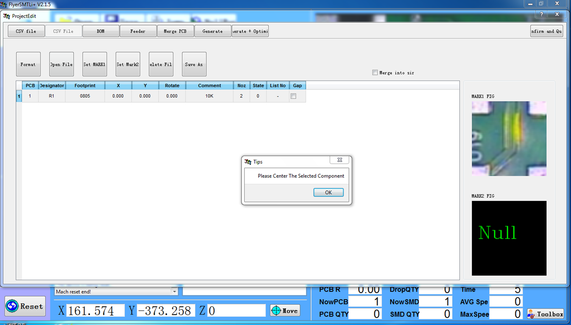
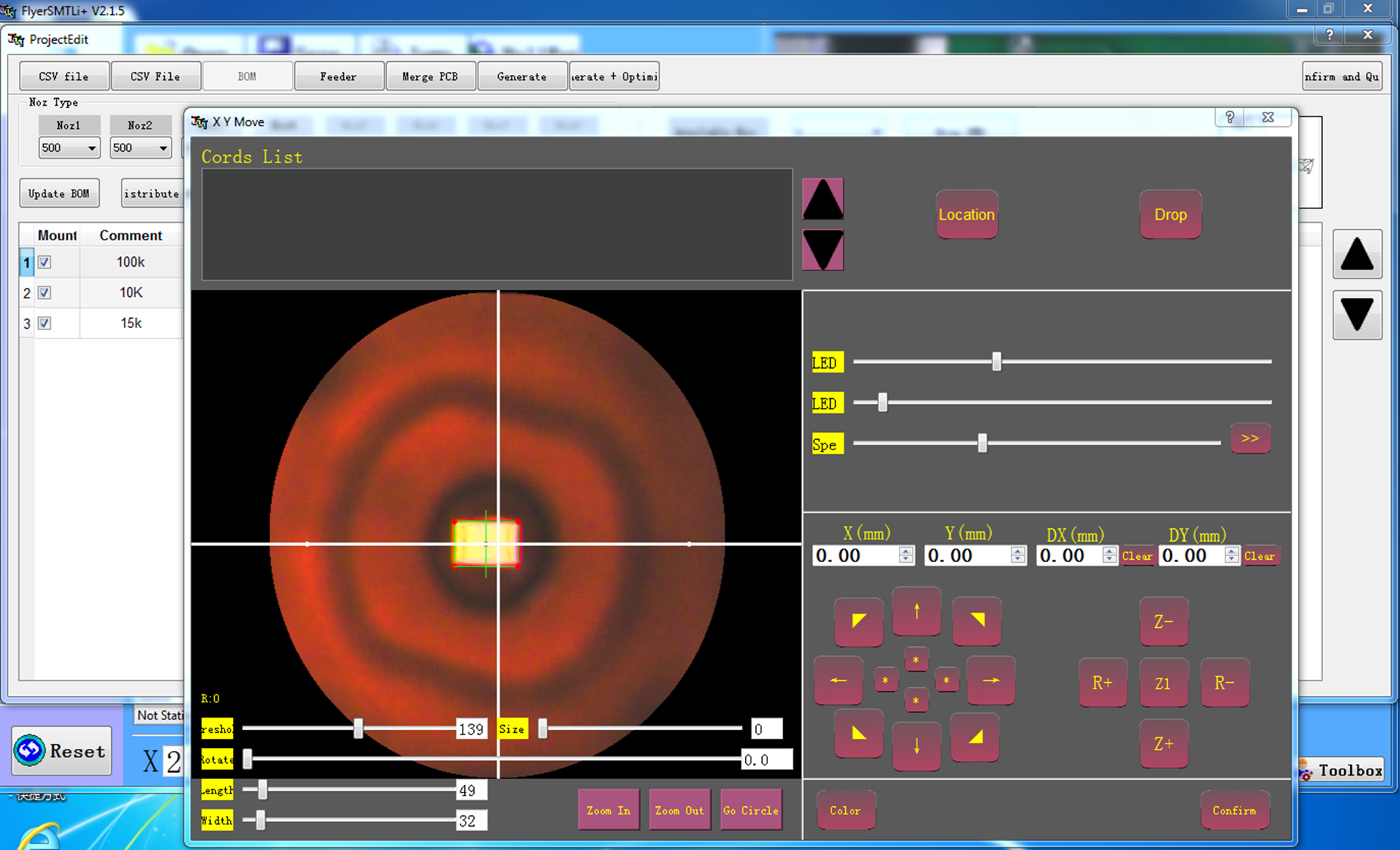
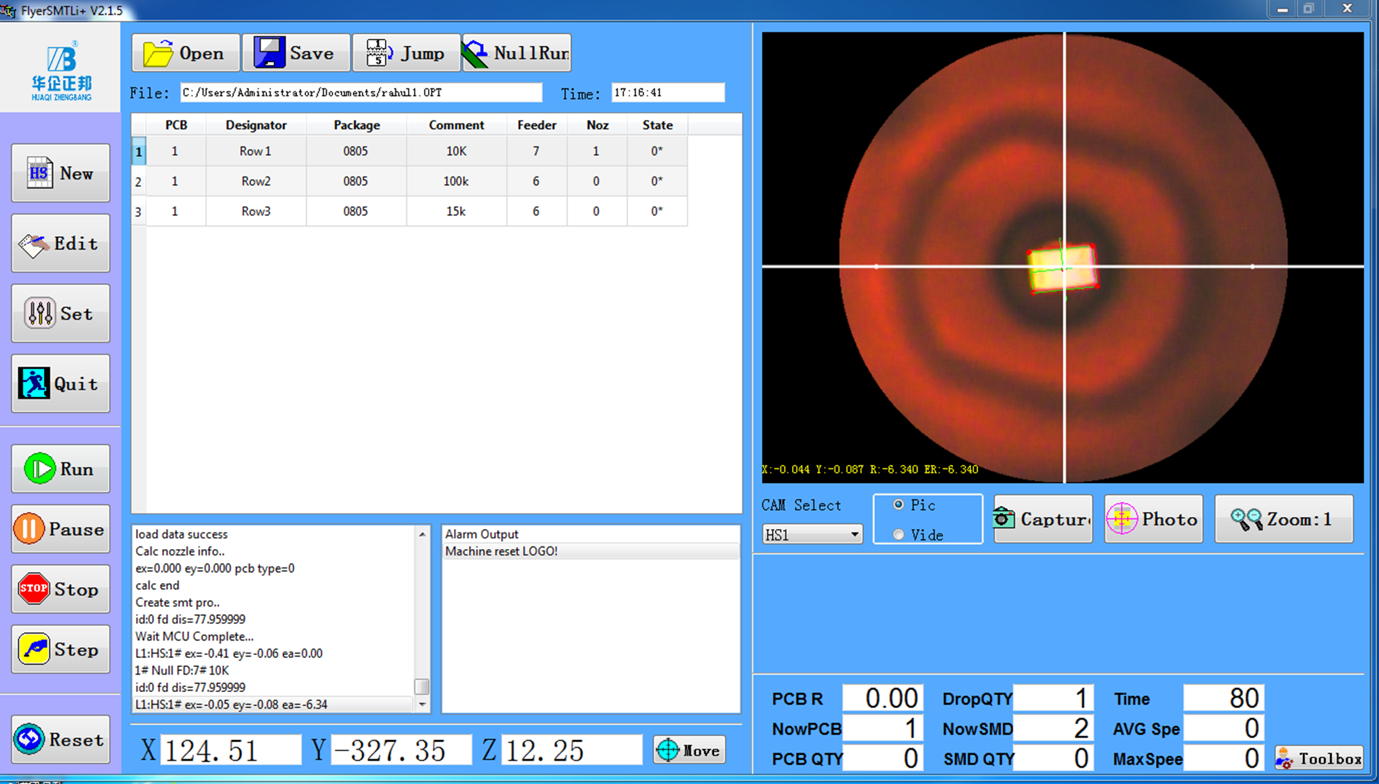
- Click on Set MARK1, then use the arrows to center the component within the red rectangle. The component can be seen at the right side of the window. Click OK and then Confirm and Quit. Before centering, the component will look like
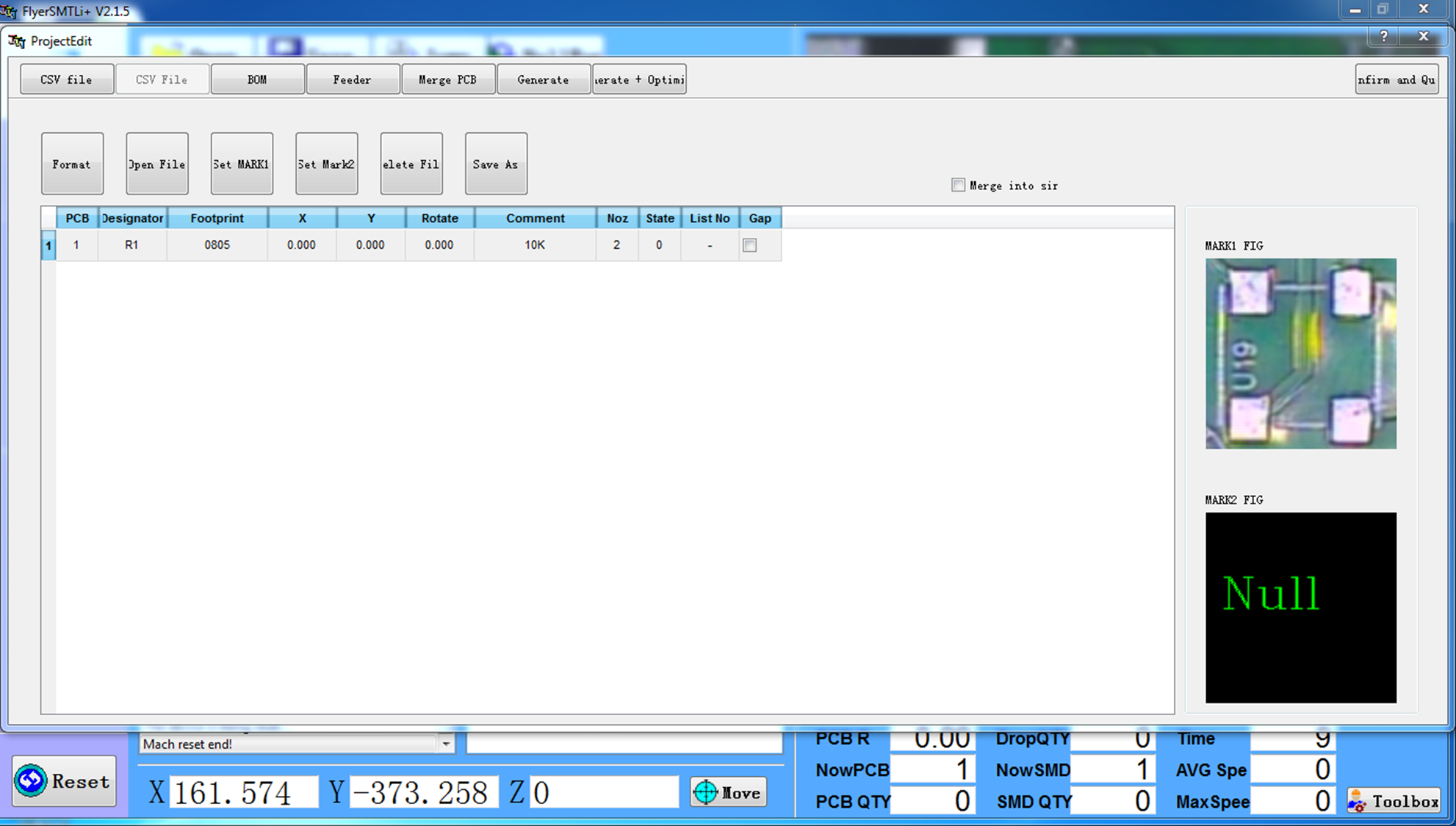
After centering, it will look like
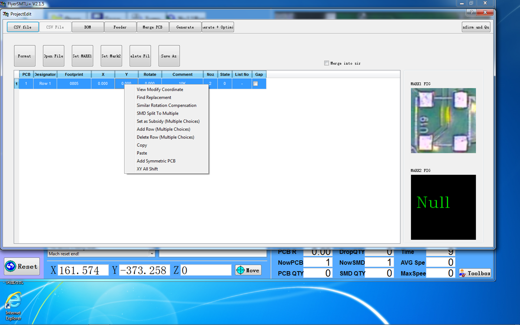
- Right-click on row1 and Add row (Multiple Choices). The row will be added. For each component, one row has to be added. Modify their cordinates by right-clicking on the row and clicking on View Modify Coordinate. This process is repeated until the positions of all the PCB components are taught to the machine.
You can change the nozzle no. in the CSV file itself at each row.
- Click on BOM and Update BOM.
- After successful updation the CSV files will appear as
Change Nozzle no. and Feeder no. in each row of the BOM as and when required.
- Click on Feeder Settings to change its setting. Click on Location for positioning the feeder. Use the arrow keys to move the feeder. Click on Feed and Confirm. The threshold value should be set before confirming. It should lie between 130 and 140.
- Click on Feeder and set picking height, downspeed, upspeed, and delay, as well as mounting height and its corresponding speeds and the delay.
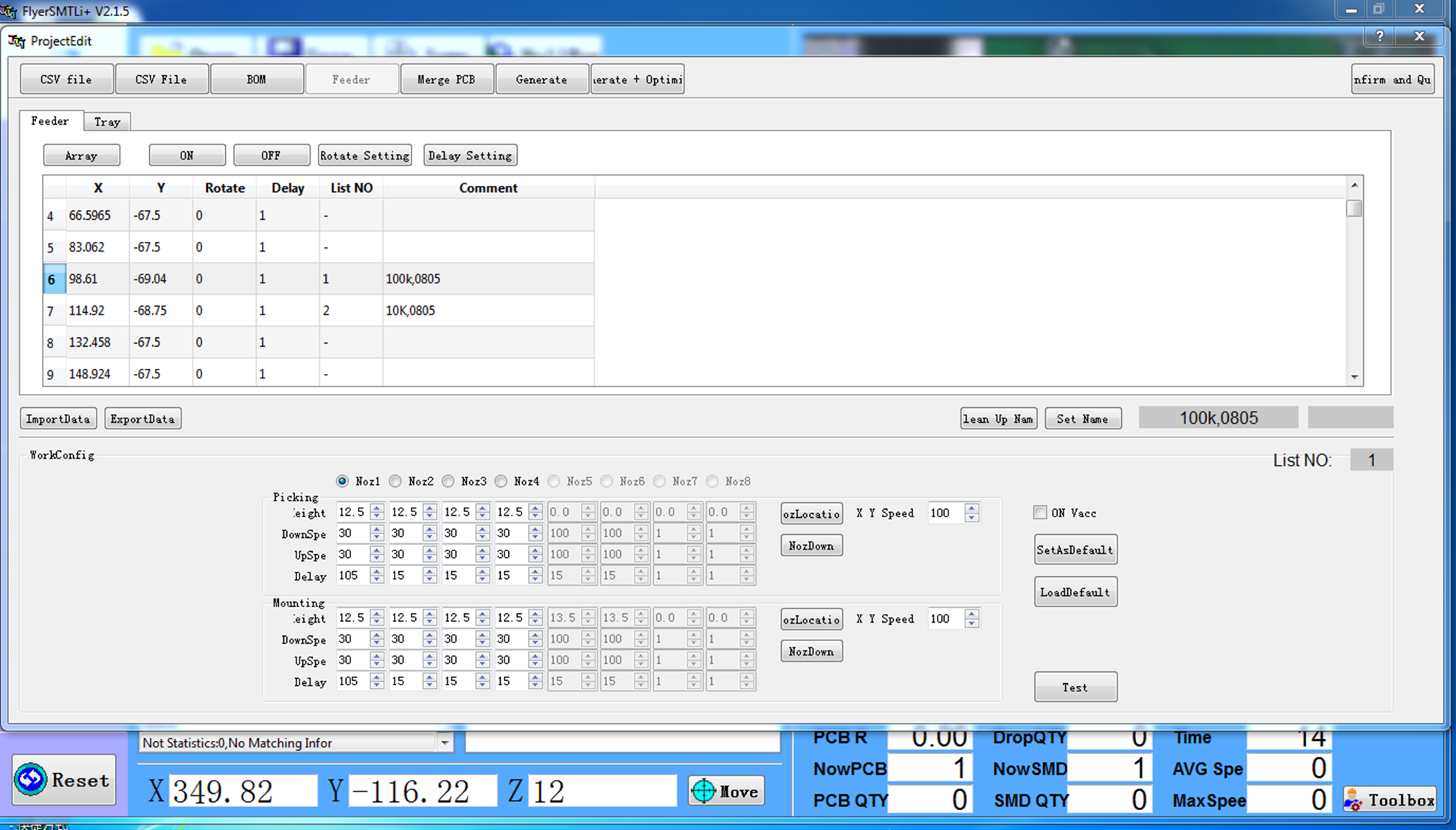
Confirm and Quit.
- The window will appear as
- The camera captures the images in real time. For test run, the machine is operated in Step mode. Click on Step for each pick-and-place movement. For the final automatic run, you just have to click on Run.
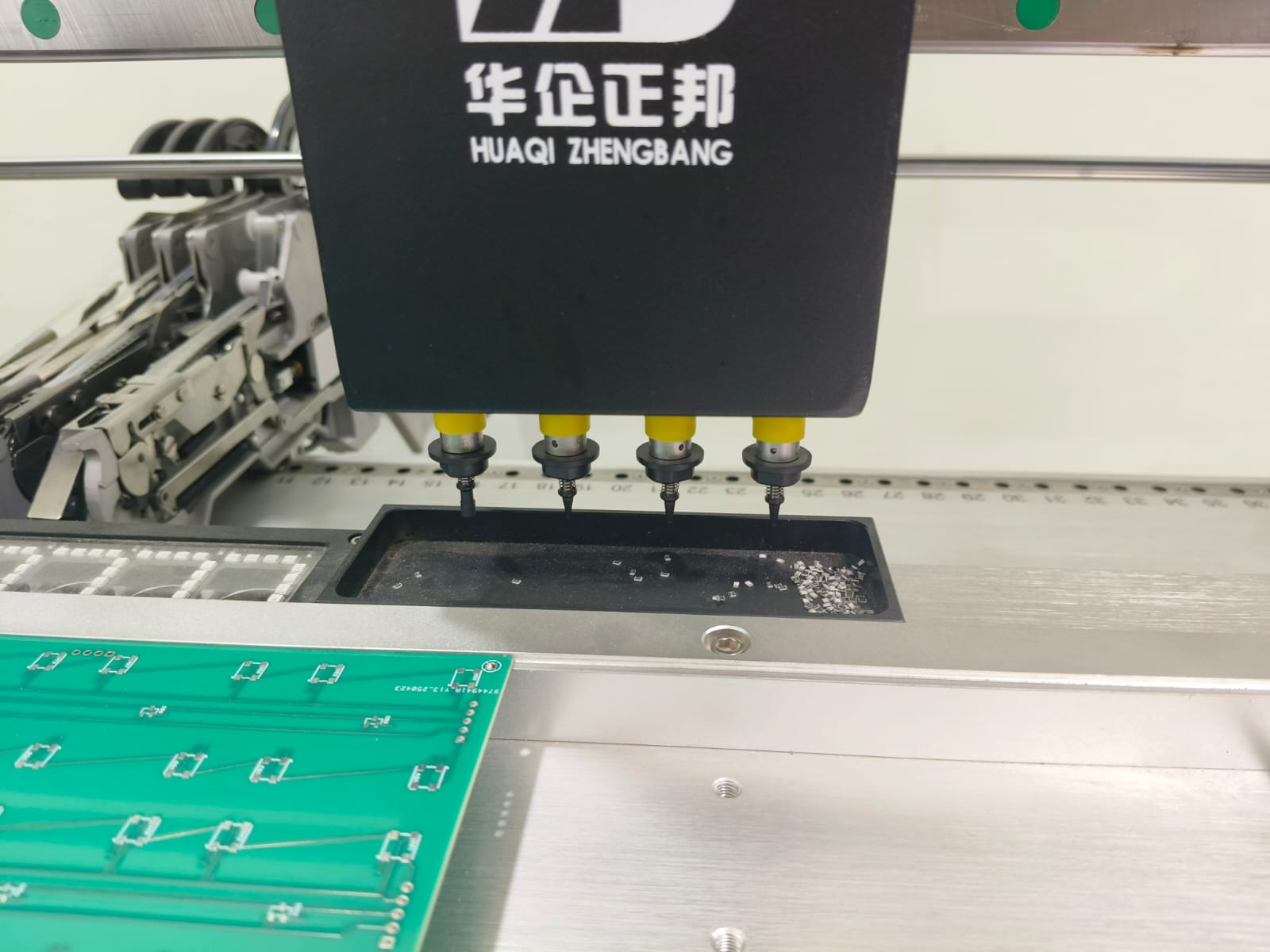
During test run, the machine will discard components in a bin as shown below
In the final run, after successful placement of the SMD component on the PCB, it will look like
After the process, you can unmount the PCB from the pick and place machine for further processing, like putting it in the reflow oven.
The user manual of the ZHENG BANG ZB3545TP Pick and Place Machine is attached below.