20251HC1: Fitness Watch

Brief Description & Functionality
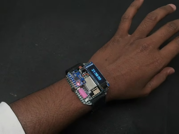
A fitness watch using Arduino is a compact, wearable electronic device designed to monitor and display basic health and activity metrics such as steps walked, heart rate, and optionally time or calories burned. Built using affordable sensors and microcontrollers, this DIY project replicates the core features of commercial fitness bands in a customizable and educational way.
The device integrates motion sensing (via an accelerometer), heart rate sensing (using an optical pulse sensor), and a display to show real-time data. It can be powered by a small rechargeable battery and housed in a wrist-mounted enclosure, making it a fully portable wearable gadget.
🧰 Components Needed
Here’s a list of parts for a basic fitness watch:
| Component | Description |
|---|---|
| Arduino Nano R3 | Main microcontroller board |
| MPU6050 | 6-axis accelerometer + gyroscope for step counting |
| MAX30102 | Heart rate & SpO₂ (blood oxygen) sensor |
| OLED Display (0.96" I²C) | Displays step count, BPM, SpO₂, and time |
| DS3231 RTC (optional) | Real-Time Clock for timekeeping |
| Li-Po Battery (3.7V) | Portable power source |
| TP4056 Module | Battery charging module |
| Resistors, wires, protoboard/PCB | For circuit connections |
| 3D-printed or plastic enclosure | To wear it on the wrist |
Here are some core components you’ll need to build the fitness watch:

Classic Arduino Nano boardArduino Nano R3 board

6‑axis motion sensor moduleMPU‑6050 accelerometer/gyro

Pulse‑oximeter sensor moduleMAX30102 heart‑rate & SpO₂ sensor
- Arduino Nano R3 board – Compact and cost‑effective microcontroller board for your project.
- MPU‑6050 accelerometer/gyro – Motion tracking to count steps and detect activity.
- MAX30102 heart‑rate & SpO₂ sensor – Optical sensor module to monitor heart rate and blood oxygen levels.
🛠️ Basic Features
- Step Counter – Use accelerometer axis data to detect steps (double‑threshold or simple peak detection).
- Heart Rate Monitor – Use MAX30102 reading with a heart‑rate algorithm (e.g. pulse detection libraries).
- Display – Show time, steps, and heart rate (BPM) on OLED, updating periodically.
- Timekeeping – Use an RTC module (like DS3231) to keep time.
🚀Written Tutorials & Project Guides
- Instructables: Fitness Tracker With Arduino
Tutorial for building a fitness tracker with accelerometer and pulse sensor, showing wiring diagrams, code, and integration of LCD display.docs.sunfounder.com+2Instructables+2Instructables+2 - CircuitDigest: DIY Arduino Pedometer
Step‑by‑step guide on counting steps using an accelerometer (e.g., ADXL335) and Arduino Nano. Easily adaptable for OLED display.YouTube+14circuitdigest.com+14Arduino Blog+14 - Hackster: Fitness Watch with Oximeter and Heart Rate
A fitness watch project using TinyCircuits modules (accelerometer, oximeter, OLED) in a compact setup with detailed code.tinycircuits.com+4Hackster+4YouTube+4 - Reddit / Arduino forum experiences
Developers integrating sensors like MPU6050 + MAX30102 + OLED and sharing wiring tips and debugging strategies.walmart.com+6Arduino Forum+6Arduino Forum+6 - TinyCircuits Custom Fitness Tracker
Example project using modular “Wirelings” (accelerometer, pulse oximetry, display, vibrating motor) to build a miniature custom tracker. Battery life and enclosure included.InstructablesArduino Forum+1Arduino Forum+1Arduino Forumtinycircuits.com+1Hackster+1 - GetFit using Nano 33 BLE Sense + Edge Impulse
Advanced tracker using embedded ML to recognize types of exercise, using built‑in sensors on Nano BLE Sense.Instructables+1YouTube+1
💻 Example Code Modules
Wire.h– For I2C communicationAdafruit_SSD1306.h– For OLEDAdafruit_MPU6050.hor custom step-counting logicMAX3010xlibrary – For heart rate sensorRTClib.h– For DS3231- Accelerometer reading via
Adafruit_MPU6050, or generically from MPU6050. - MAX30102 using
MAX3010xlibrary and pulse detection. Adafruit_SSD1306for the display.
🎥 Learn from Video Tutorials
🧩 Simple Workflow
- Pick your board & sensors (Arduino Nano, MPU6050, MAX30102, OLED).
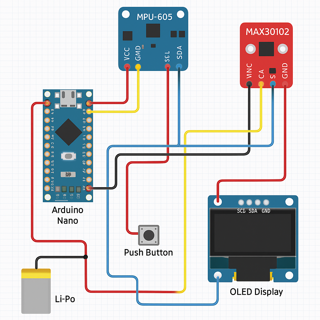
- Wire sensors to board following I²C pinouts.
- Install necessary Arduino libraries:
Adafruit_MPU6050/WireMAX30105(or MAX30102),heartRate.hAdafruit_SSD1306 - Start simple: read accelerometer and show step count; integrate heart rate next.
- Build enclosure—3D print a case or use watch band holders to make it wrist‑worn.
- Refine power usage, add battery and charging module (e.g. LiPo + TP4056).
🚀Circuit Diagram
🧑🔧Skills Required
- Arduino programming (C/C++)
- Circuit simulation
- PCB design
- PCB milling
- Manual soldering
- SMT soldering
- Electronic testing
- CAD modelling
- 3D printing (FDM)