PCB Screen Printing
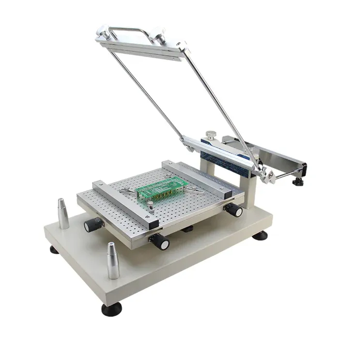
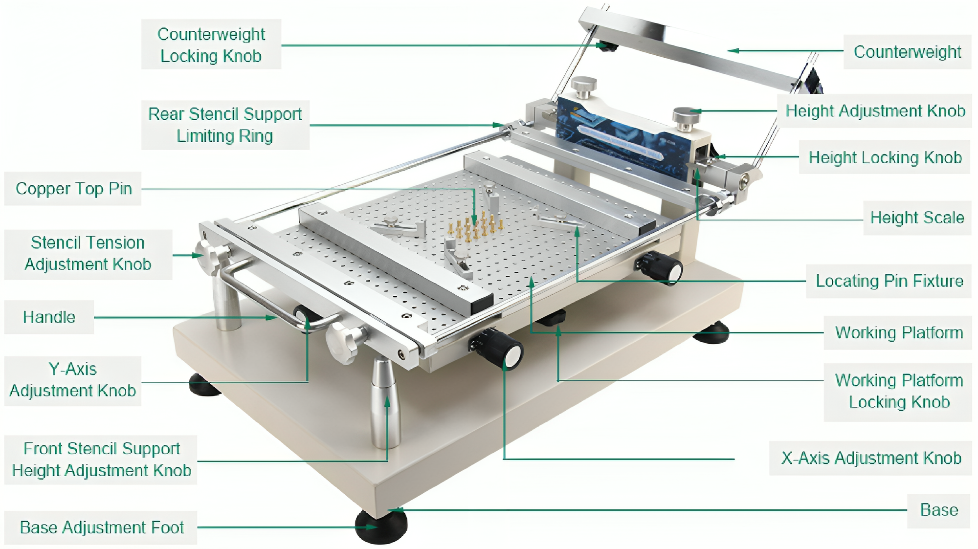
iTECH PTR-C300 Manual Stencil Printer is a precision printing product designed for the single- and double-sided circuit board solder paste or red glue printing requirements of frameless screen printing stencils. A comprehensive image including all its components is shown below.
A step-by-step operating procedure to apply solder paste on the PCB are given below:
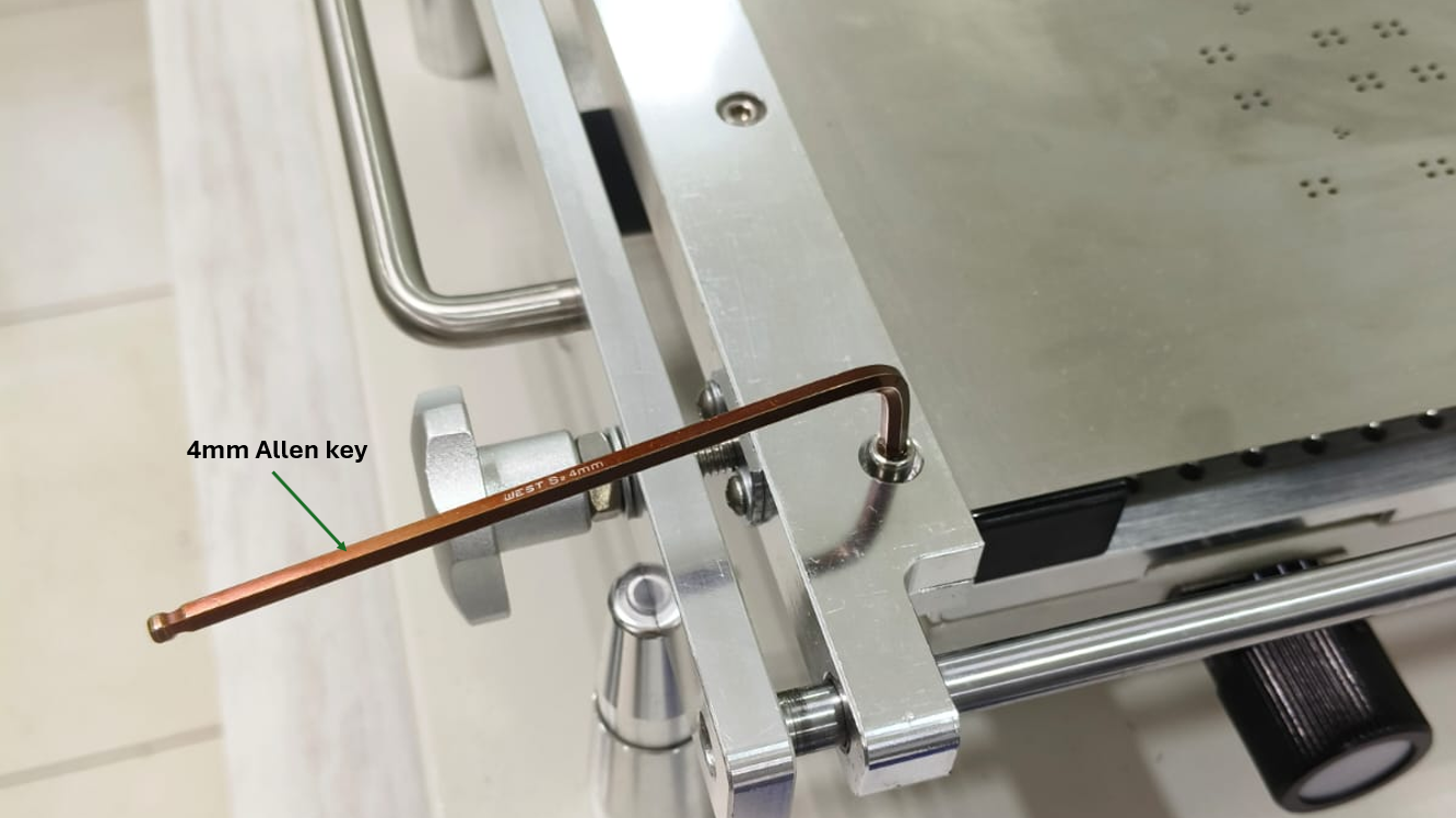
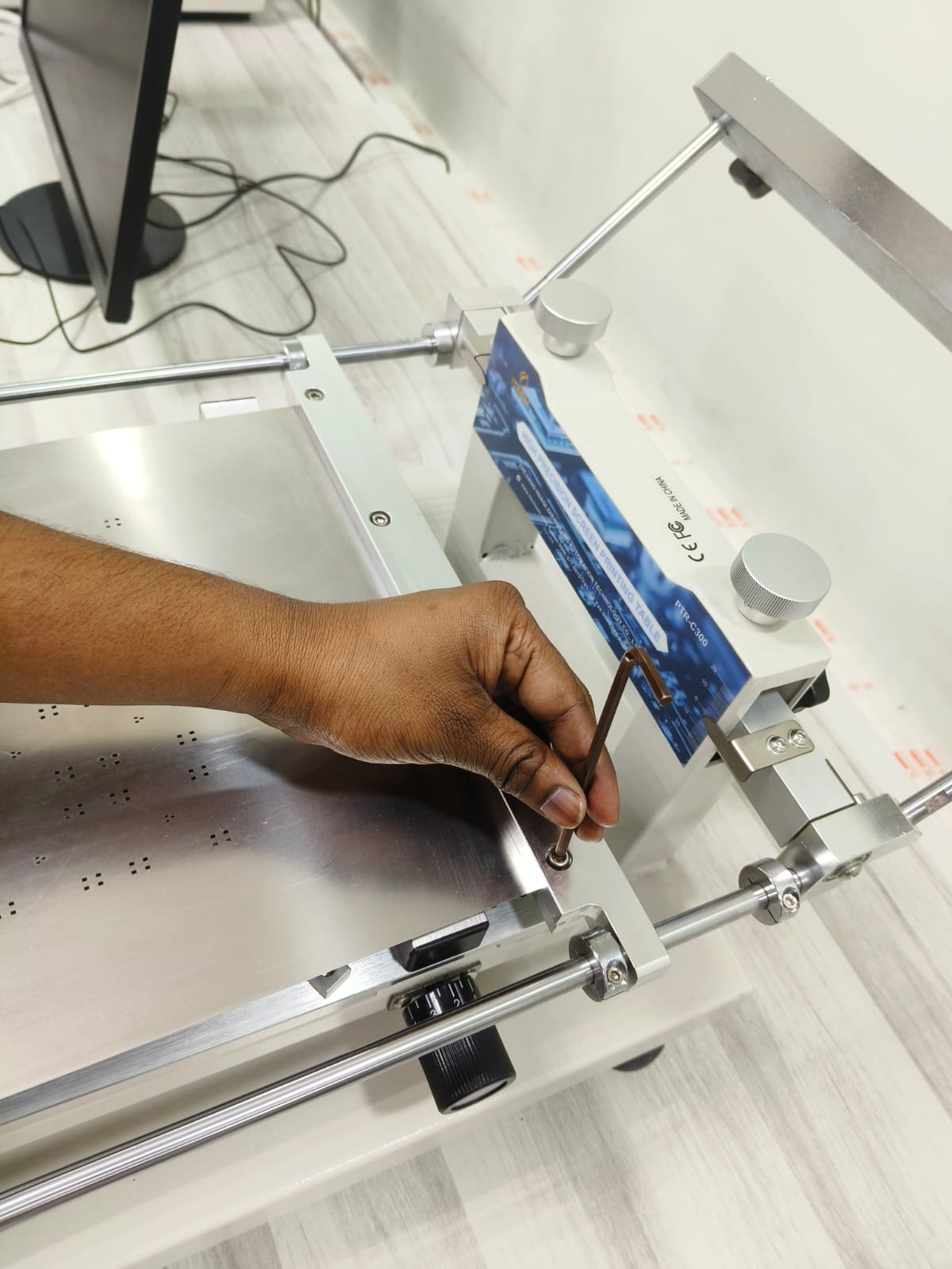
Step 1: Unmount the silkscreen from the "front and rear clamps" using a 4 mm Allen key when a new PCB arrives.
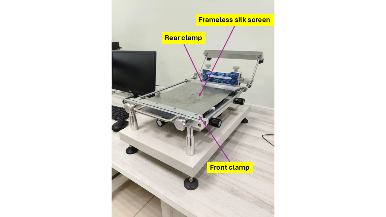
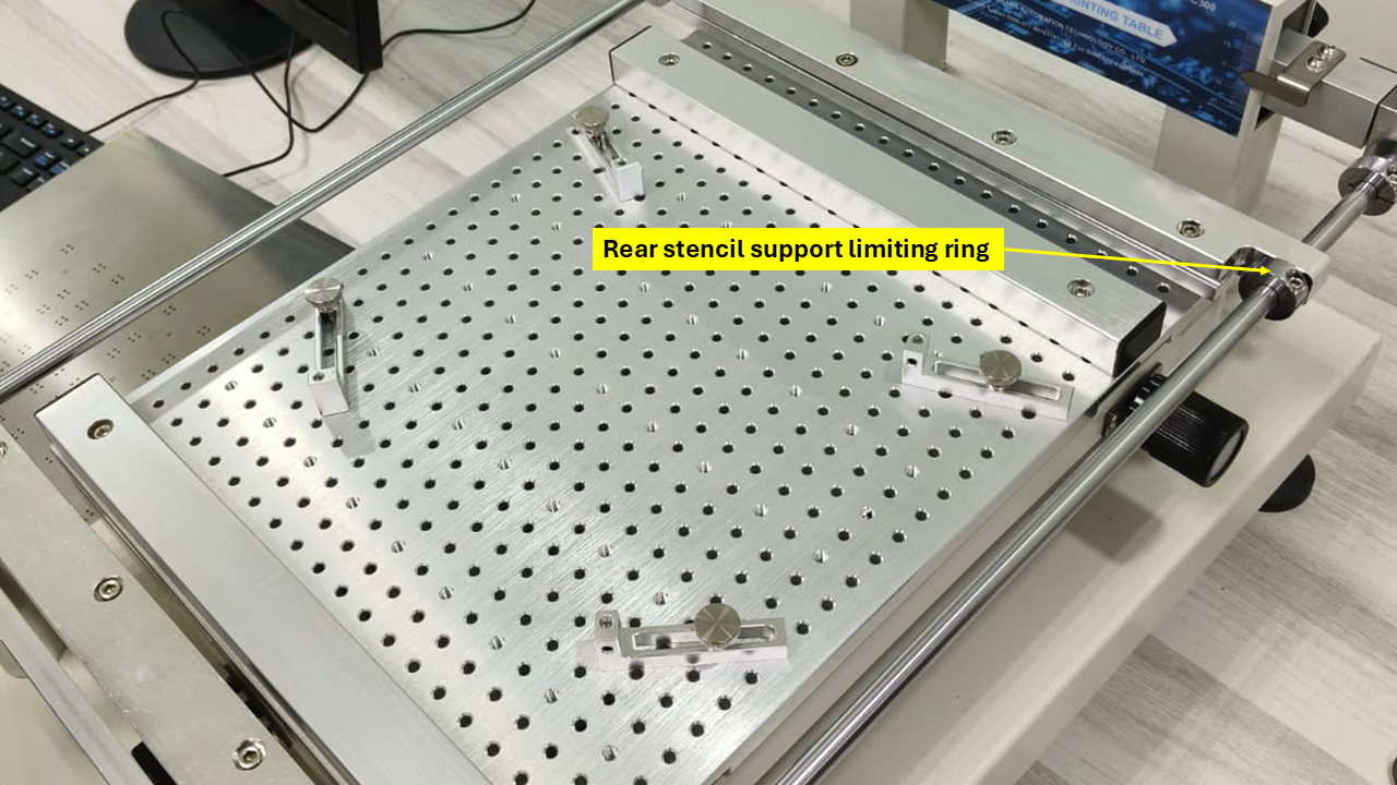
Step 2: After unmounting, the machine will appear as shown below:
The clamps should be adjusted according to the PCB size and shape. The "rear stencil support ring" can be loosened by a 3 mm Allen key.
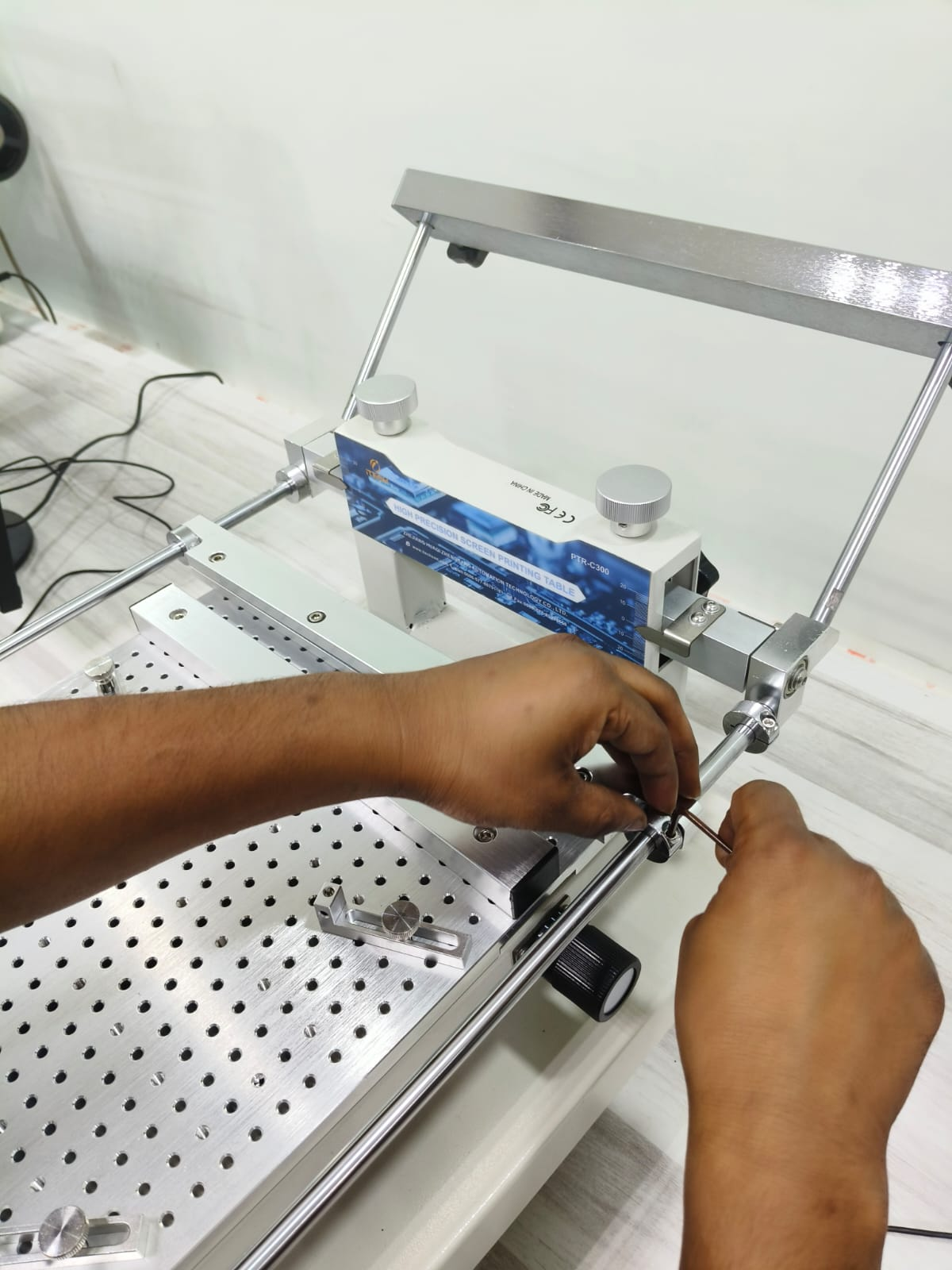
Step 3: A frameless PCB silkscreen is securely held in place using the front and rear clamps. The screws of the clamps are tightened by the 4 mm Allen key. After confirming its placement, the "rear stencil support ring" is tightened by a 3 mm Allen key.
Step 4: The tension of the silkscreen is adjusted by the "stencil tension adjustment knob" to hold the stencil firmly.
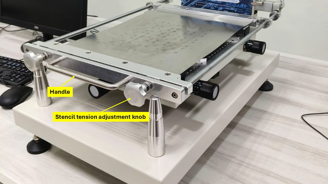
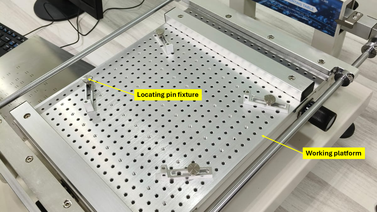
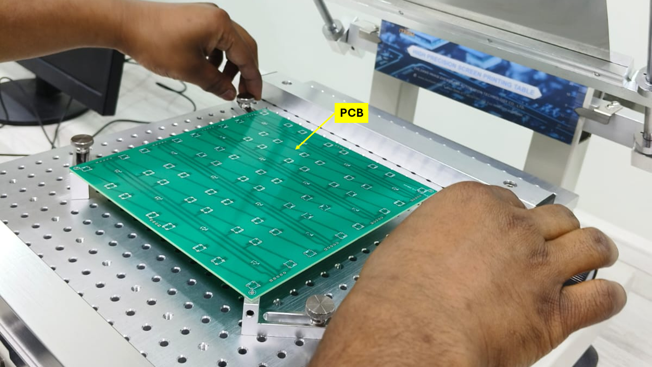
Step 5: The silkscreen is then moved up by the "handle," and the "locating pin fixtures" are properly tightened to the "working platform" using the "locating pin fixtures." The placement of the fixtures is based on the PCB size and shape.
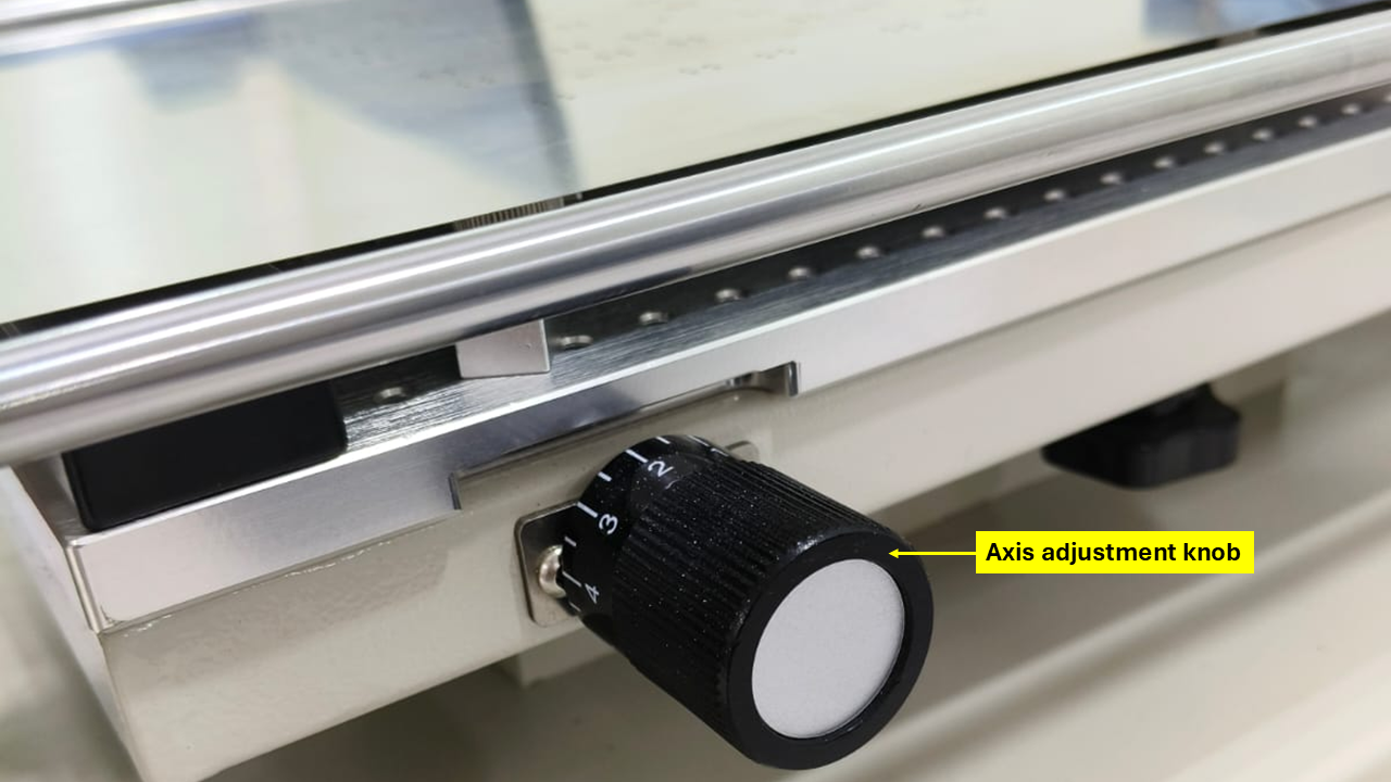
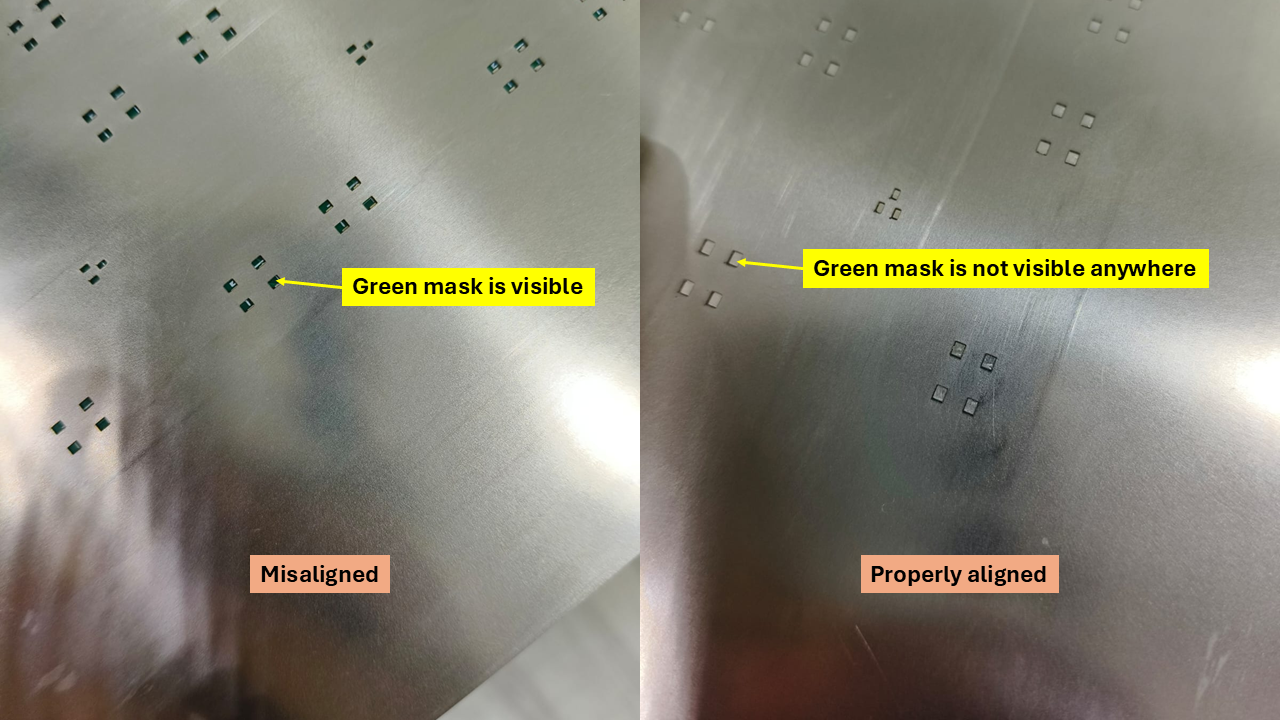
Step 6: Move down the silkscreen to place it over the PCB. The openings on the stencil may not properly match with the PCB markings. For fine adjustment of the working table, "X and Y axis adjustment knobs" should be used.
The self-explanatory figures provided below confirm the alignment of the stencil with the PCB.
Step 7: The solder paste is applied on the stencil by a squeegee blade. A schematic diagram of applying the solder paste is shown below.
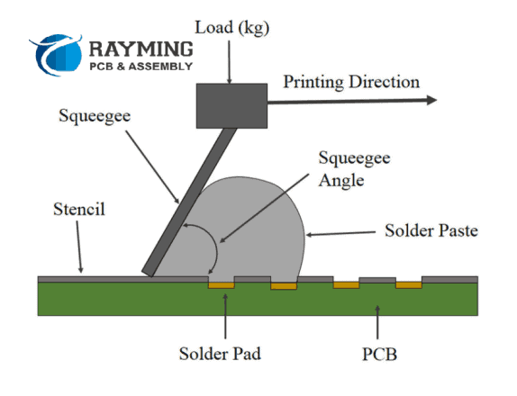
Openings on the stencil allow the paste to sit on the solder pads where the SMD components should be placed. The video demonstrates the entire process: