Electronic Testing: DC Power Supply
A DC power supply is a device that provides Direct Current (DC) electricity to an electrical load. It converts AC (alternating current) from the mains or other sources into a stable and regulated DC output that can power electronic circuits, devices, or systems.
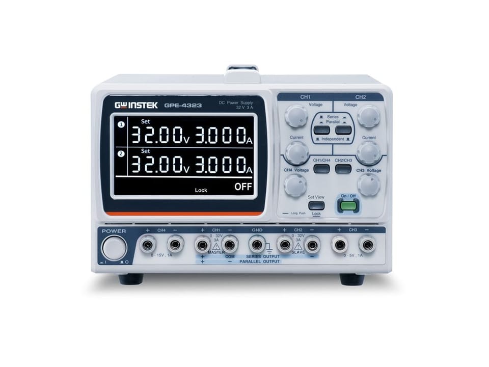
The GPE‑4323 is a 4‑channel, 212 W linear DC power supply, part of the GPE‑X323 series. It features:
- CH1 & CH2: 0–32 V / 0–3 A each (independent)
- CH3: 0–5 V / 0–1 A
- CH4: 0–15 V / 0–1 A
Some of the important features that may come into action during electronic testing are
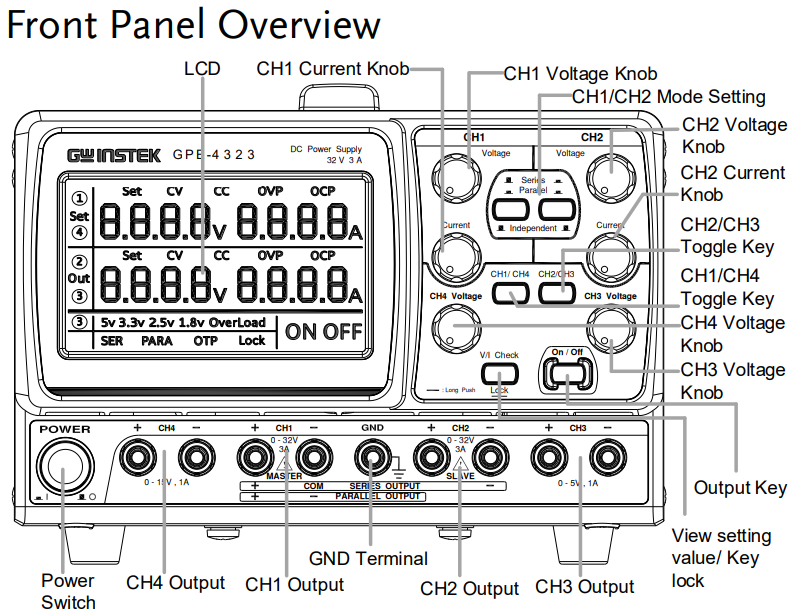
- 4.3‑inch LCD display with digital panel control for settings and readbacks
- Set View function lets you verify voltage/current settings before enabling output
- Key Lock feature to prevent accidental parameter changes—especially for CH1/CH2 knobs
- Output ON/OFF control both locally and via remote analog interface (Remote I/O)
The GPE‑4323 is ideal for engineering labs, educational environments, and product development bench testing—especially where multiple isolated voltages, high precision, and flexibility are needed.
- Use the tracking series mode when you need higher voltage and the parallel mode when you need higher current.
- The set-view and key-lock functions help ensure safe operation and prevent accidental changes.
- The remote on/off interface makes it easy to integrate with external control systems.
To work with this device, one needs to follow the steps mentioned below.
- Connect the AC power cord to the rear panel socket.
- Press the power switch to turn on the power. The display will first display all the LCD segments before showing settings for each channel.
- To load the cable connections, turn the terminal counterclockwise and loosen the screw. Then insert the cable terminal. Turn the terminal clockwise and tighten the screw.
- Select CH1/CH2 series or parallel mode according to your requirement.
- You can toggle the connection mode of CH1/CH2 by using different combinations of the mode selection key (CH1/CH2 mode setting).
- The lock function of the GPE-4323 can be used when you need to keep the output voltage constant to avoid the load from being damaged due to inadvertent operation. The voltage lock takes the present channel settings as the reference levels. The voltage lock function only applies to CH1 & CH2. Press the LOCK key (for more than 2 seconds) to lock the voltage knob operation for CH1 & CH2 in the front panel. The Lock icon will become lit.
- The OUTPUT key is not affected by the lock operation. It is normal for the output voltage to have a fluctuation of around 20 mV after the voltage settings are locked.
- Connect the load to the front panel terminals, CH1 +/−, CH2 +/−.
- Use the voltage and current knob to set the CH1 output voltage and current.
- Use the voltage and current knob to set the CH2 output voltage and current.
- Make sure the Series/Parallel key is not activated (both the SER and PARA icons are off).
- Press the Output key to turn on the output. The Output key will be lit and the ON icon will appear on the LCD display. The CV or CC icon appears on the LCD to indicate the output status for each channel.
For example, a 12-volt DC motor has been supplied power through this device. The video of the rotating spindle of the motor is attached below.
Useful Resources
User Manual of Multi-output DC Power Supply (GPE-1326/2323/3323/4323 Series)