CAD Design
CAD stands for Computer‑Aided Design.
It is software that engineers and designers use to create accurate drawings and 3D models of parts, machines, and structures on a computer instead of drawing them by hand.
When you use CAD, you can:
- Draw shapes and designs with perfect accuracy.
- Quickly change dimensions or features without starting over.
- View your part from any angle in 3D before making it in real life.
- Check how different parts will fit together.
Learning CAD early will make your future projects much easier. Almost every field of engineering—mechanical, civil, electrical, aerospace—uses CAD to design and develop products. It also helps you to understand how parts are made and assembled.
Here, we will introduce the basics of CAD by actually modeling a simple part step by step in Autodesk Inventor.
Example : Designing of Bearing Mount
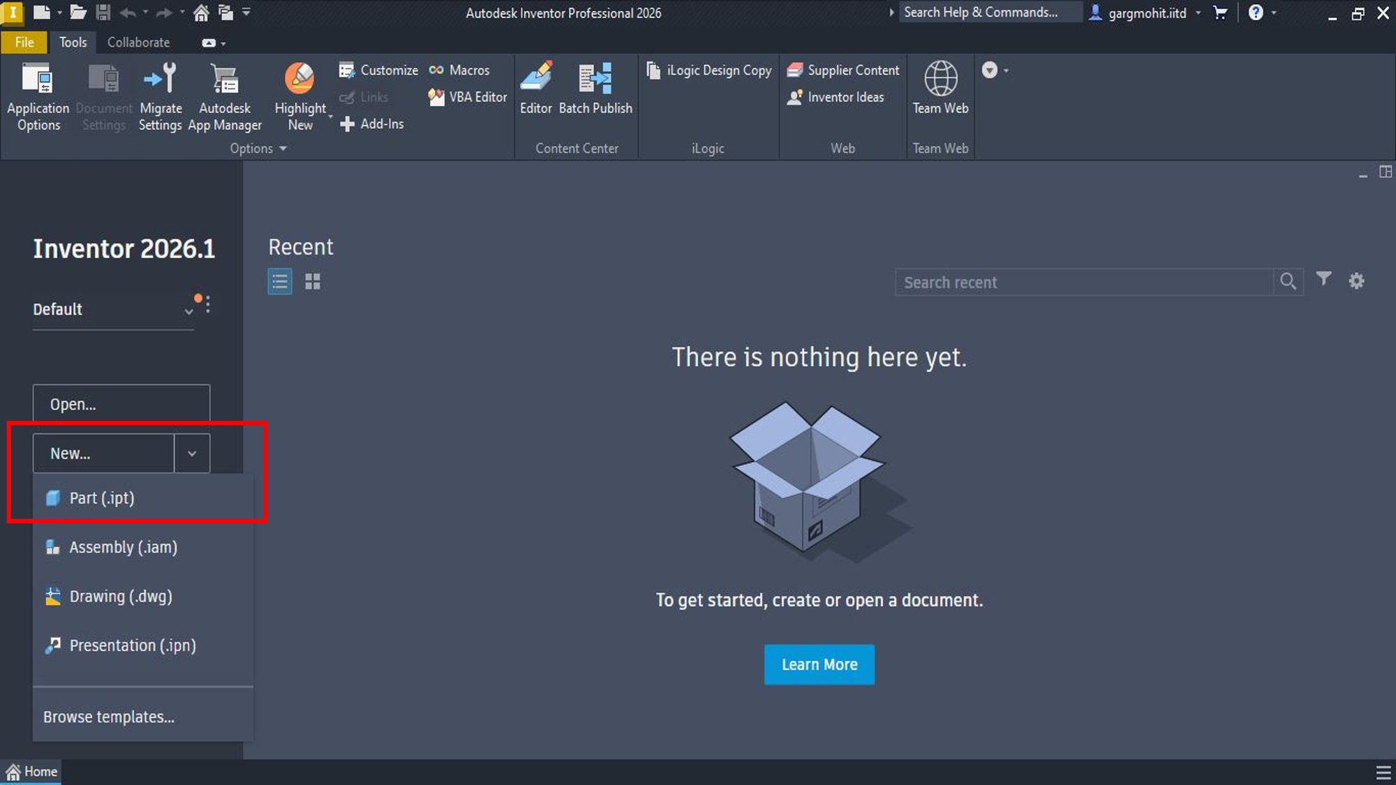
✅ Step 1: Start a New Part
Open Autodesk Inventor → Click on New → Select Standard.ipt (part file).
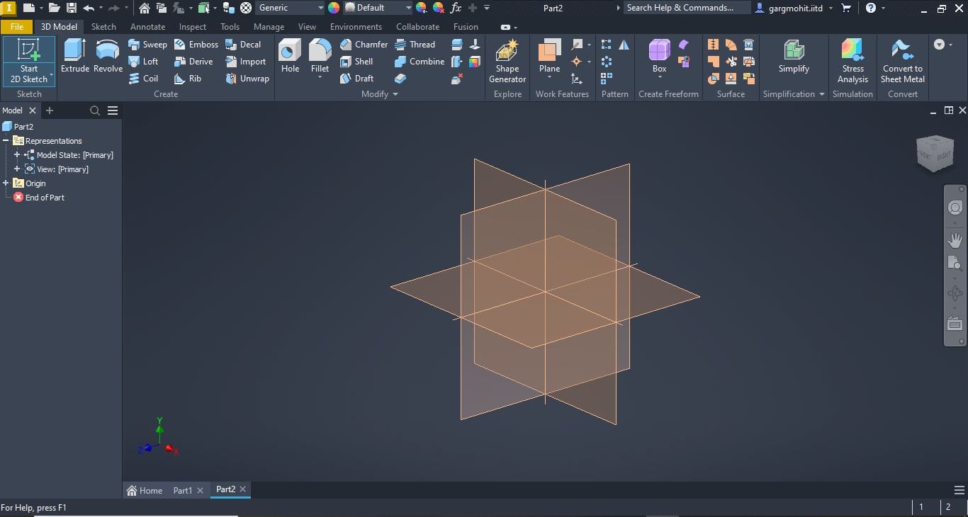
✅ Step 2: Create a 2D Sketch
Click on Start 2D Sketch → Choose a plane (e.g., XY plane).
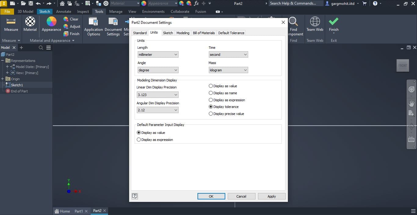
✅ Step 3: Select the units for Dimensioning
Click on Tools → Then click on Document Settings
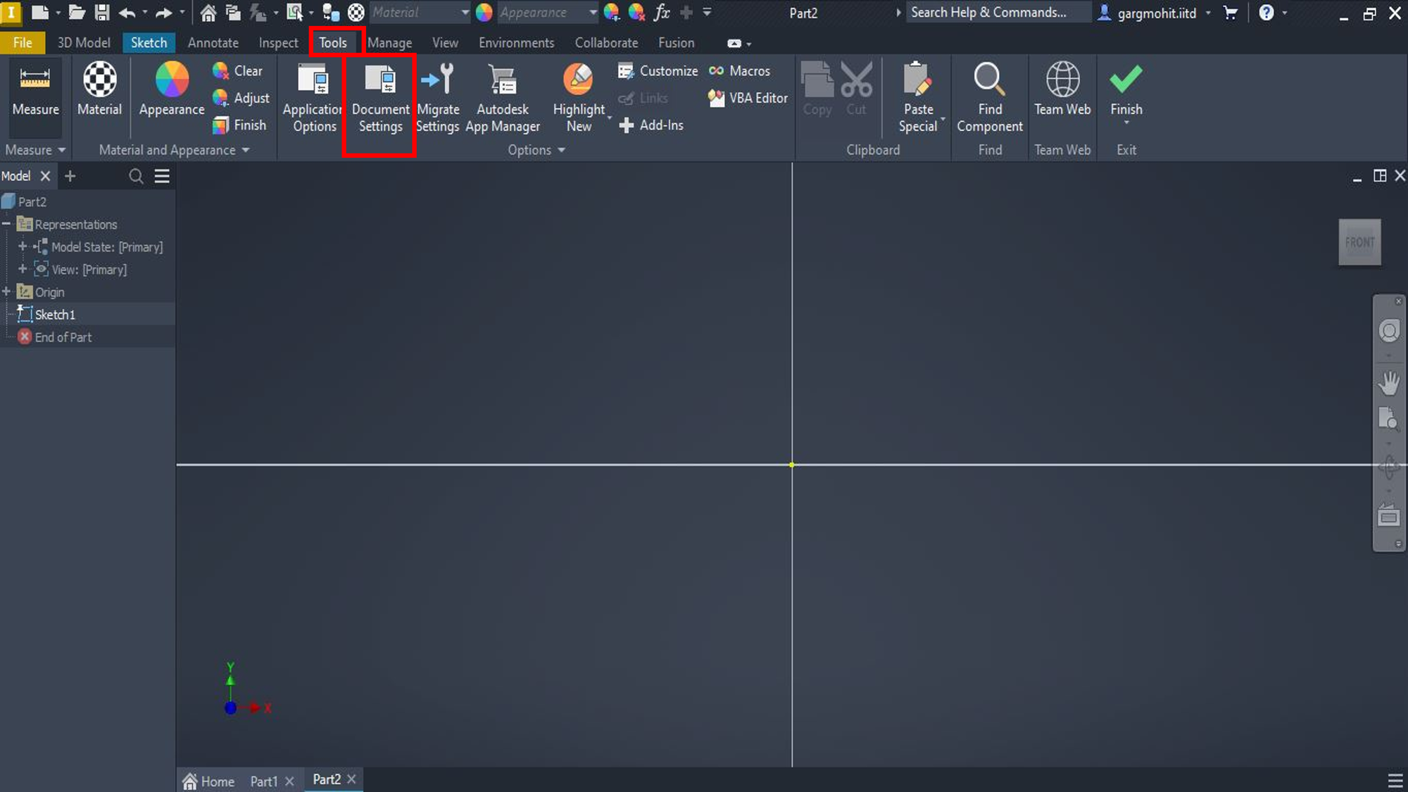
Select the suitable units and Apply
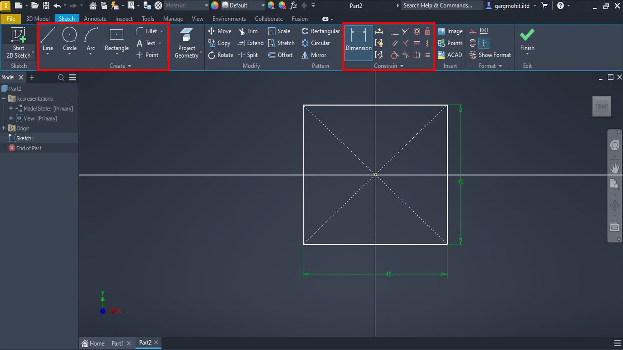
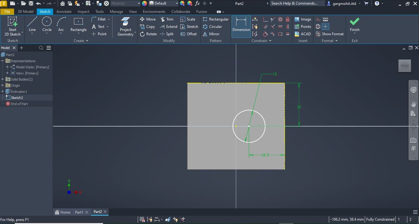
✅ Step 4: Draw the Base Profile and add Dimensions
Use the Line or Rectangle tools to draw the outline of the bearing mount and use dimension tools to give it proper dimensions.
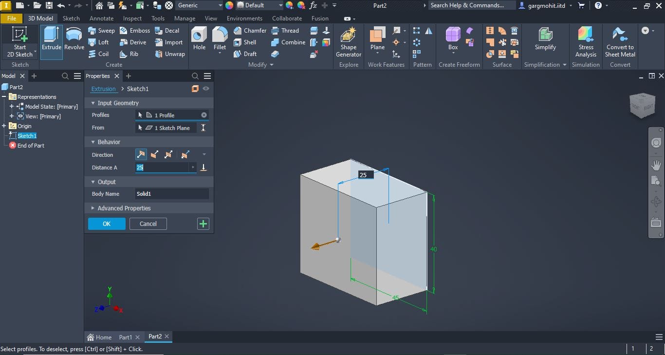
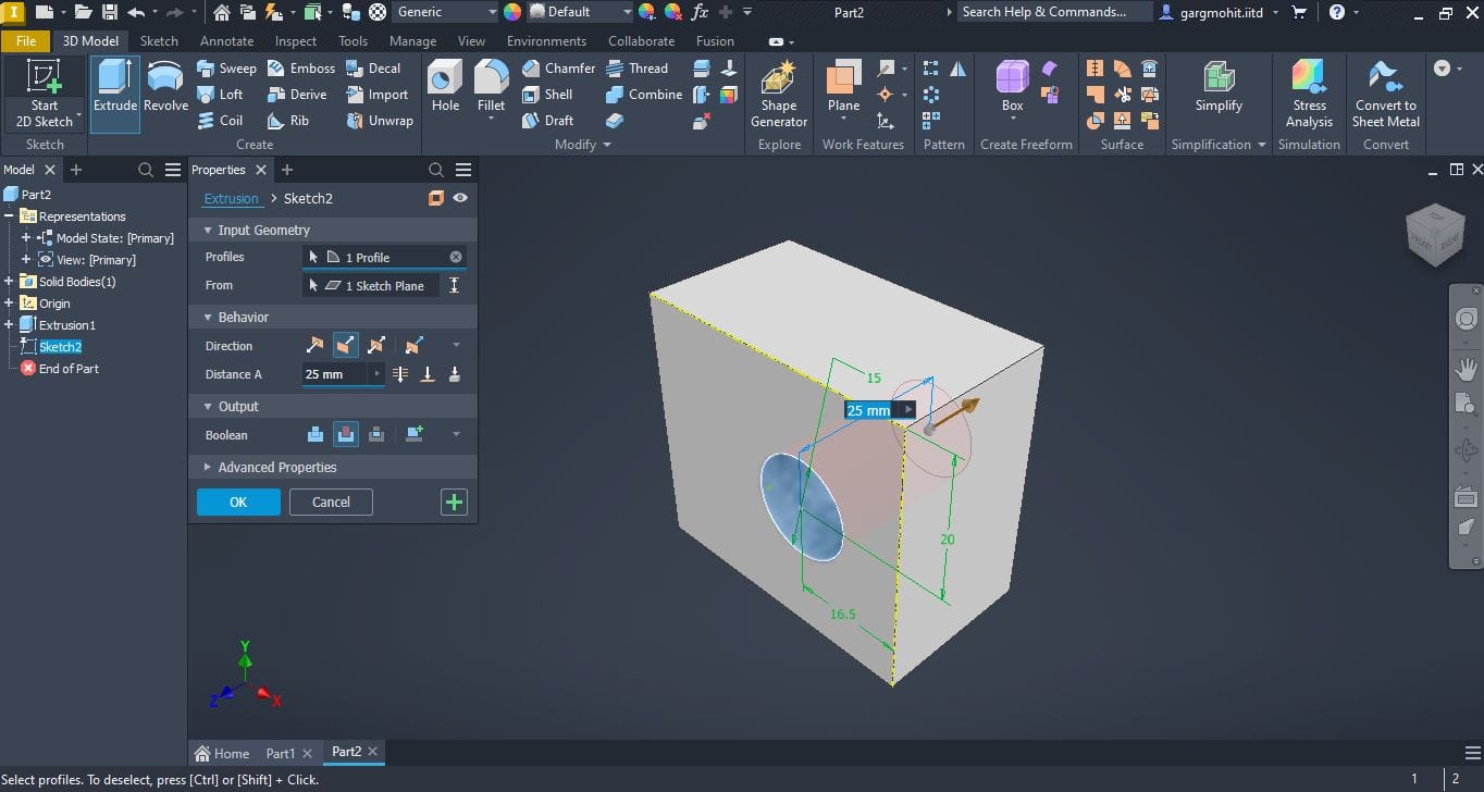
✅ Step 5: Finish Sketch and Extrude
Click Finish Sketch → Go to 3D Model → Select Extrude → Enter extrusion distance.
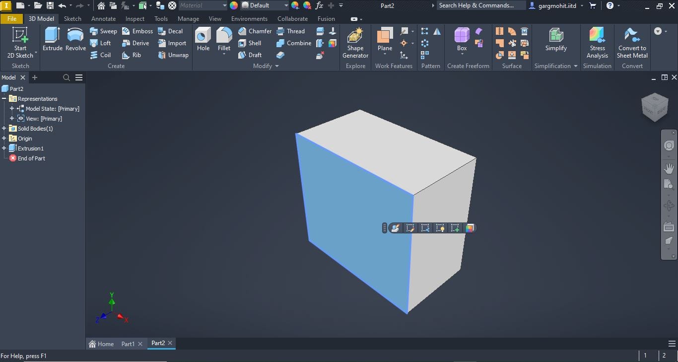
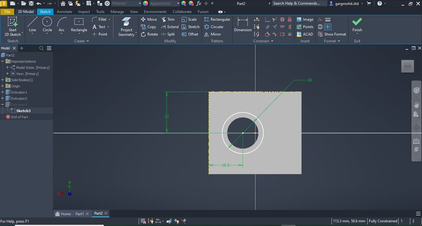
✅ Step 6: Select the face for further drawing of features
Click the face for sketching → Draw the feature → Dimension it.
✅ Step 7: Extrude Cut
Click the extrude feature→ click extrude cut option → Give the depth of feature
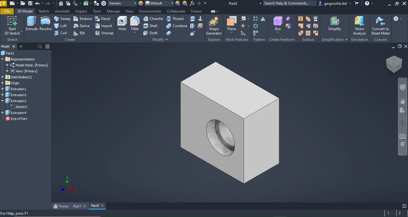
✅ Step 8: Counter-boring
Click the face for counter bore → draw the circle at desired location and dimension → extrude cut it to desired dimension for counter-boring. (repeat for another face as well).
✅ Step 9: Review the final part and Save it