Autonomous Robot with Smart Obstacle Avoidance
The robot is designed to automatically cover a pre defined area row by row and smartly avoid obstacles on its way using Arduino Uno and Ultrasonic Sensor.
The design also uses motor encoders that send signals to the Arduino regarding the distances covered that are useful for calculations related to total area coverage and the deviation done in case of obstacle avoidances, this allows the robot to safely cover its required area and path. The motors are controlled using motor drivers.
The heart of the mechanical frame is built using Aluminum Extrusions onto which the wheels are assembled. The main driving wheels are coupled to the DC Motor using ball bearings and shafts to prevent damage to the DC Motor.
Mechanical Setup
Components
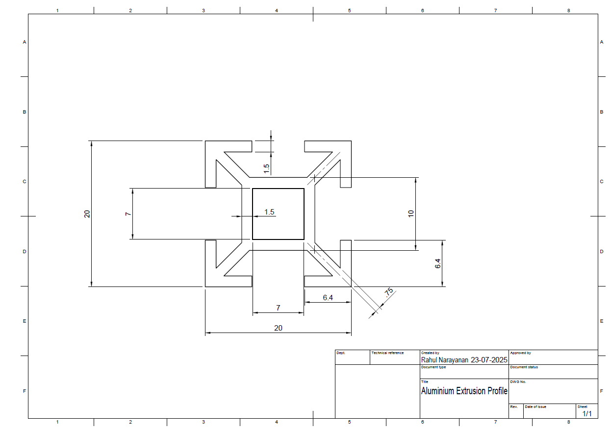
- Aluminium Extrusions
- Aluminium Extrusions Joining Brackets
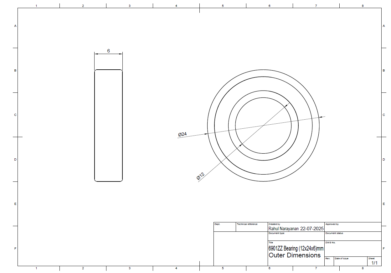
- Ball Bearings (12x24x6mm)
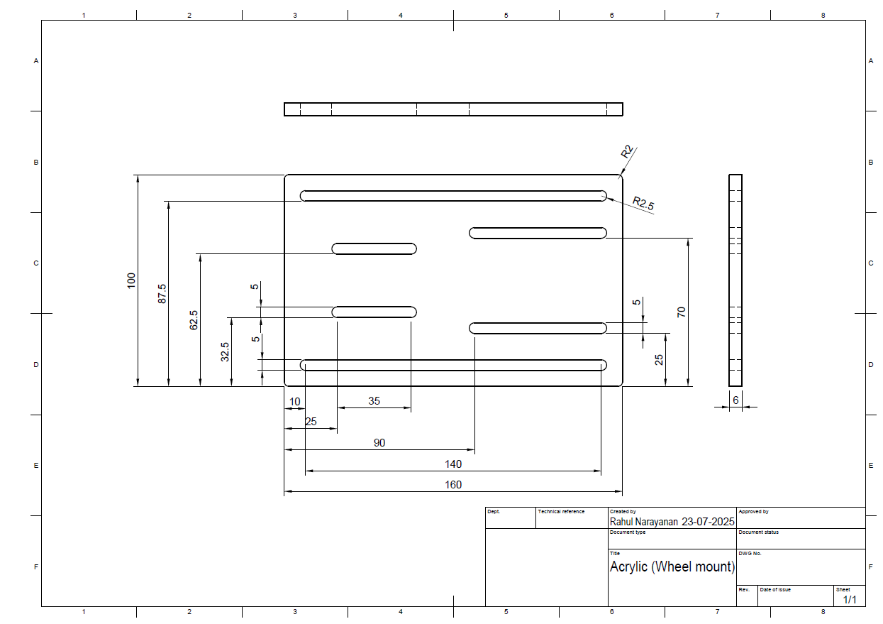
- Acrylic – For wheel mount
- Acrylic – For Caster wheel mount
- Acrylic – For top cover
- T nuts
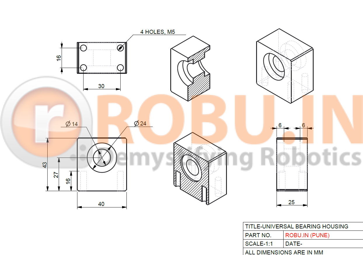
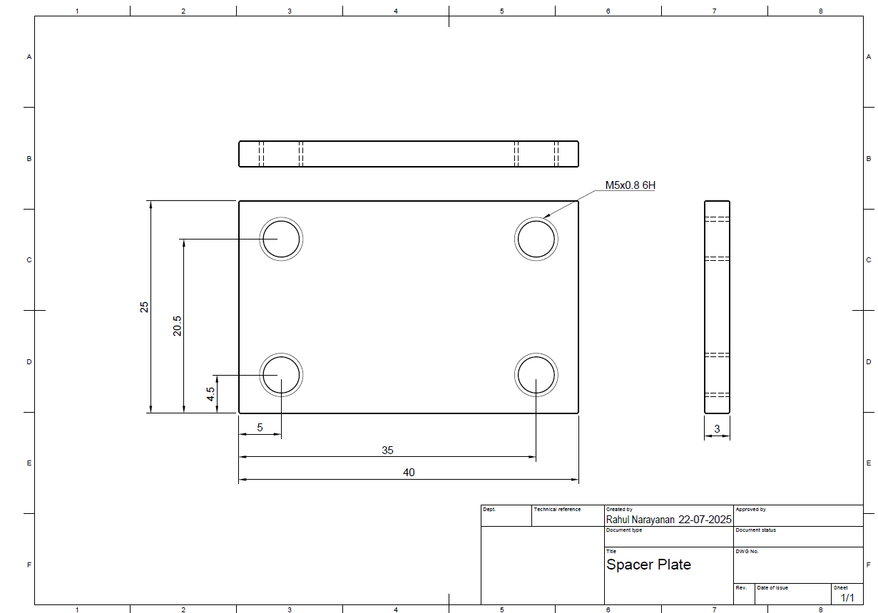
- Universal Bearing Housing + Spacer Plate
- Caster Wheel
- DC Motor
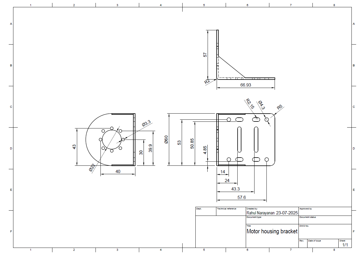
- DC Motor Bracket
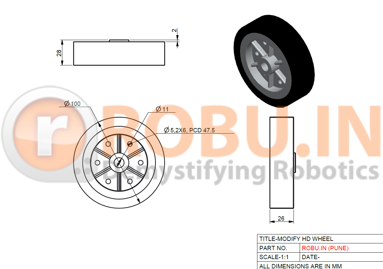
- HD Wheels (100mm)
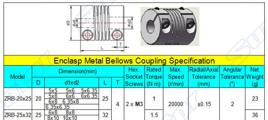
- Flexible Coupling
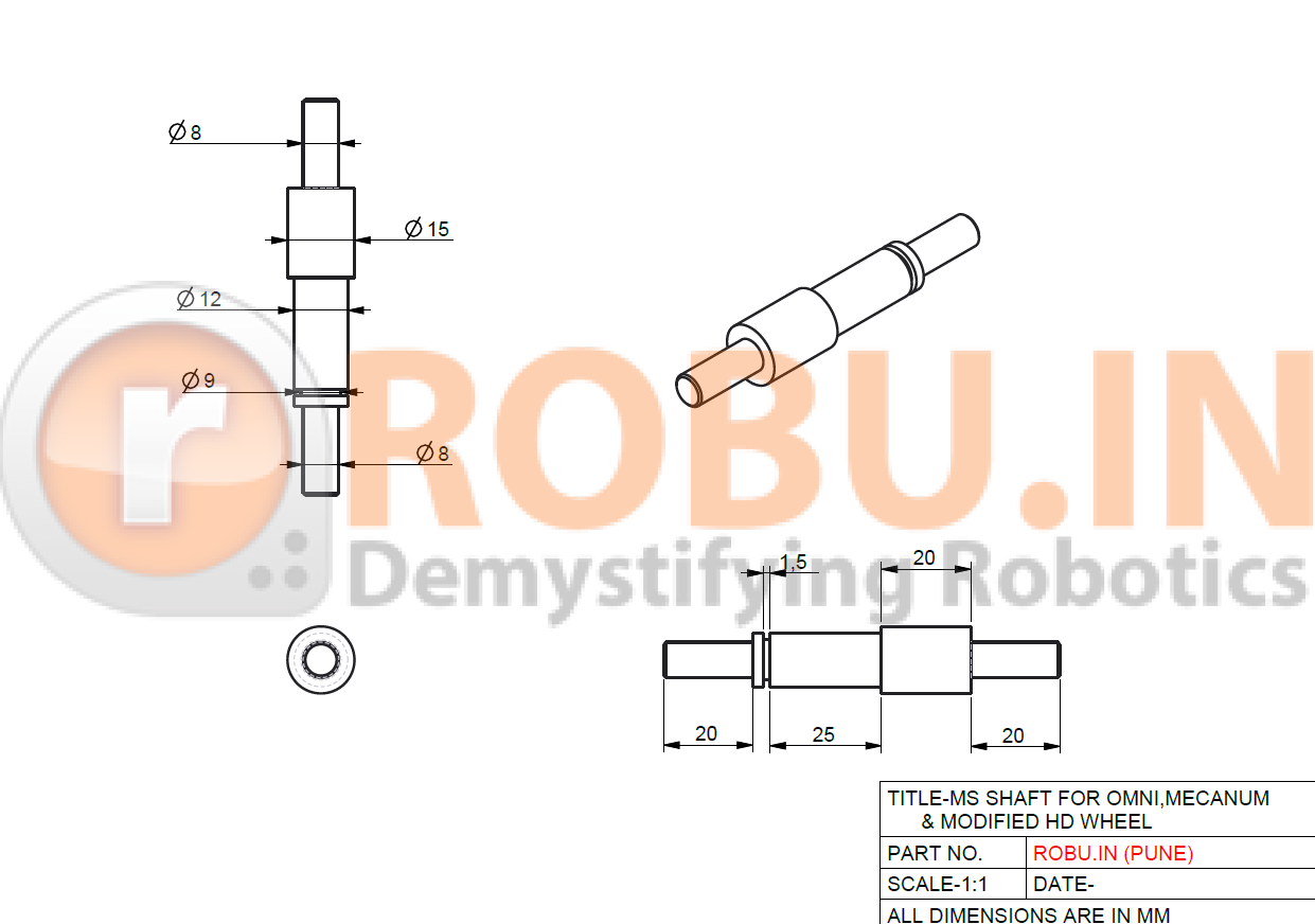
- MS Shaft for HD Wheel + Shaft collar to Keep it in Place
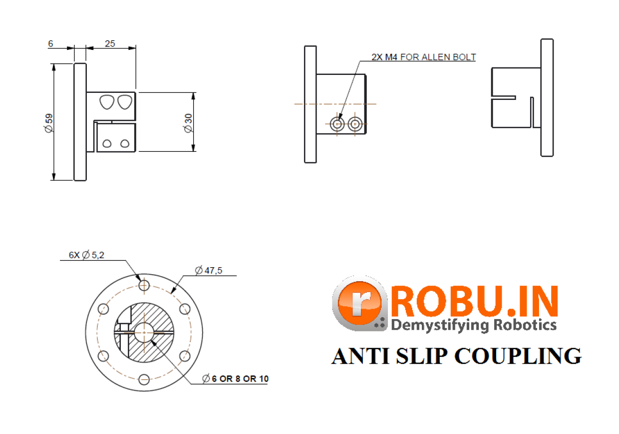
- Antislip Motor Coupling
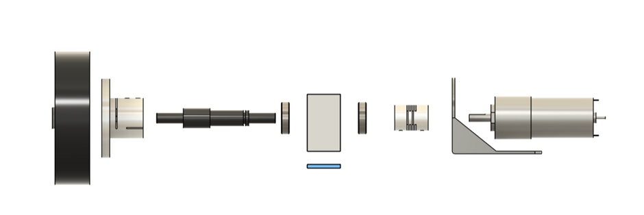
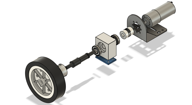
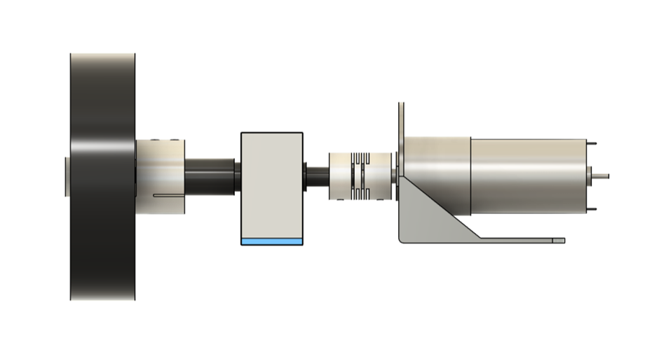
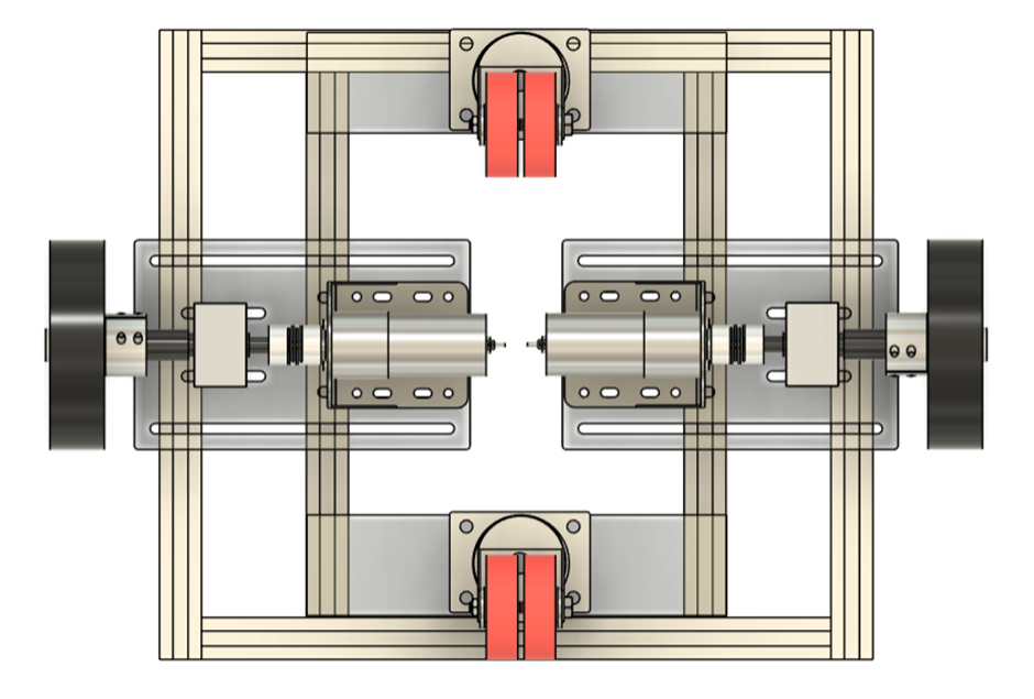
Assembly Guide – Wheel Module
A singular module of the driving wheel consists of
1) HD Wheel
2) Antislip Motor Coupling
3) MS Shaft for HD Wheel (locked in place using shaft collar)
4) Ball bearings
5) Universal Bearing Housing with a spacer plate
6) Flexible Coupling
7) DC Motor and Motor Bracket
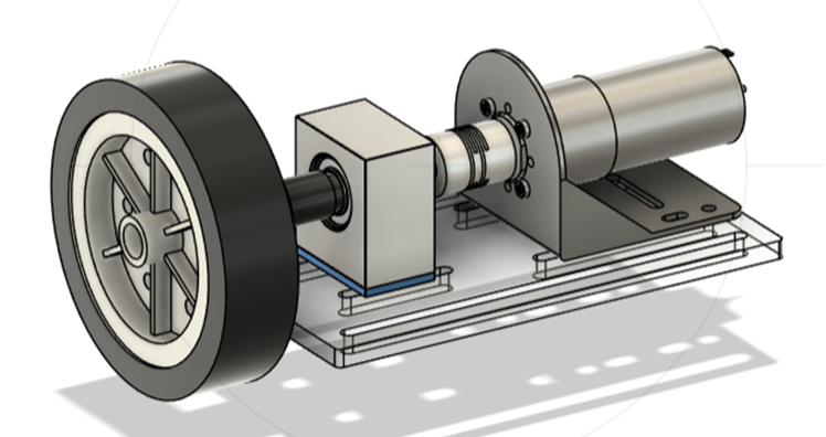
This module is mounted to an acrylic plate and attached to the extrusion frames.
Attached with Acrylic
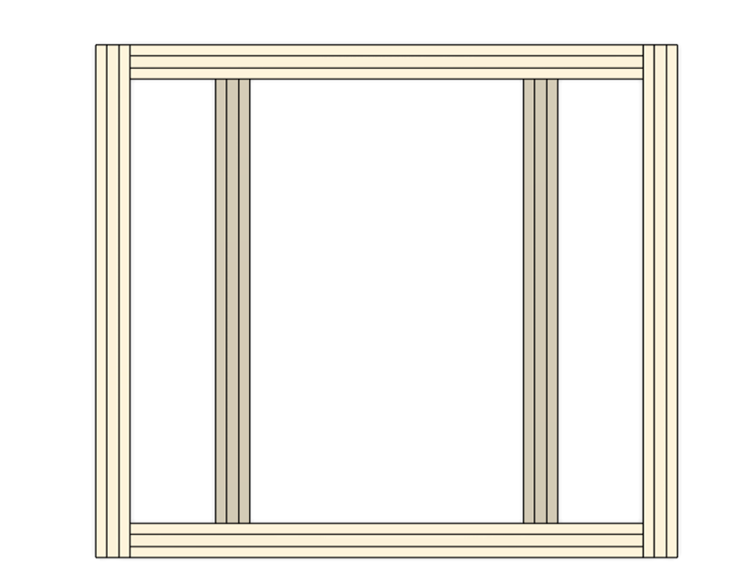
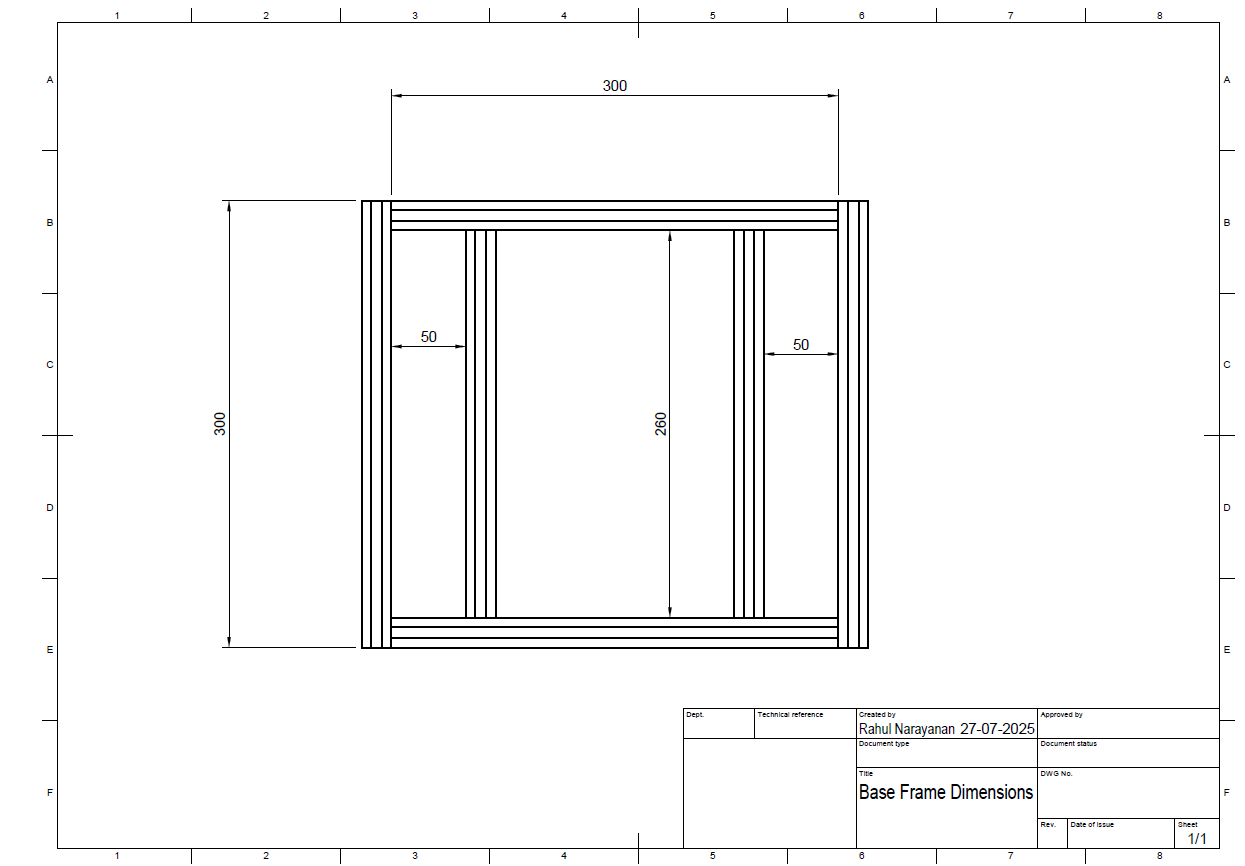
Assembly Guide - Base Frame
4 x 300mm Extrusions on Outer Side
2 x 260mm Extrusions on Inner Side
Note- The frames are to be joined with Joining Brackets. (not highlighted for easier readability, refer to the 'Assembled Mechanical Design' with Joining Brackets installed)
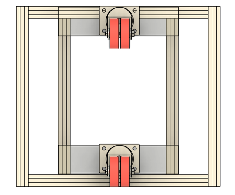
Caster Wheel Mount to Frame
- Mount the Caster Wheel to ‘Acrylic – For Caster wheel mount’
- Attach to Frames
- Fasten using Screws
Note: Thickness of Acrylic – For Caster wheel mount + Caster Wheel must be adjusted to be equal to the height of the robot from the ground.
Thickness of the Acrylic hence can vary based on the dimensions of the caster wheel.
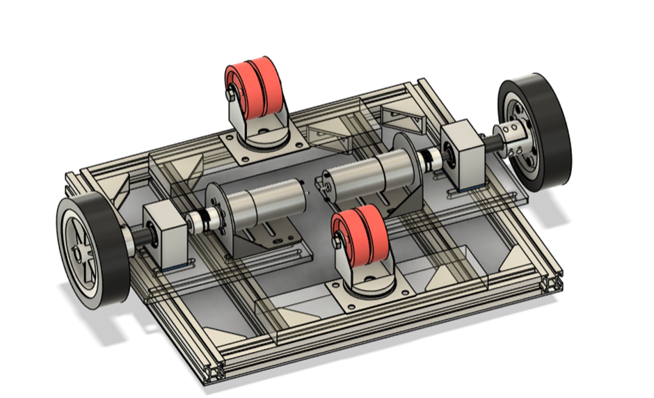
Assembly Guide - Mounting Wheel Module
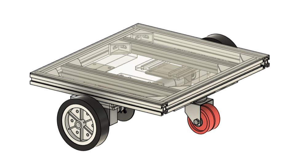
Assembly Guide - Top Cover
Another thin 3mm acrylic plate is used to cover the entire top of the robot on which electronic components are assembled and mounted. (color for representative purpose)
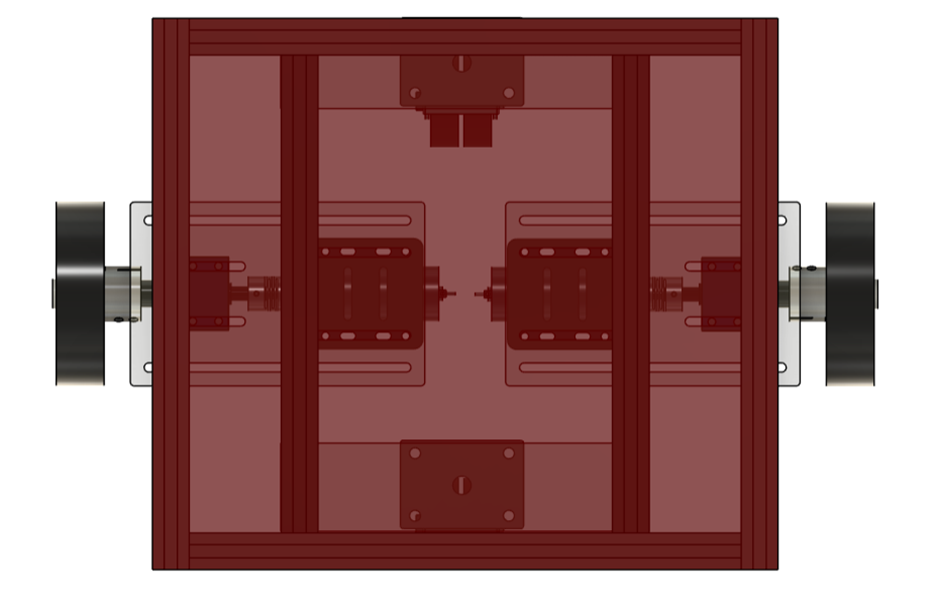
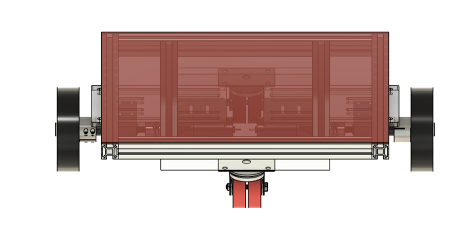
Assembled Mechanical Design
Electronic Setup
Components
- L293D / L298N motor driver/etc. (based on current requirements)
- Arduino Uno R3
- 2 Motor Encoders
- 3 Ultrasonic Sensors (HC-SR04)
- 12V battery
- Jumper wires for connections
Component Labelling
- 3 Ultrasonic Sensors labelled: FRONT, LEFT, RIGHT
- 2 Motor Encoders labelled: LEFT AND RIGHT
Ultrasonic Connections
- VCC of each Ultrasonic sensor to 5V Power Pin of Arduino Uno R3 (achieved using breadboard rail)
- GND of each Ultrasonic sensor to GND Power Pin of Arduino Uno R3 (achieved using breadboard rail)
- Note - All grounds (Arduino and Battery to be connected, as in schematic)
- Trigger pins of ultrasonic – TRIG, Echo pins- ECHO (FRONT_TRIG refers to the trigger pin of the front ultrasonic sensor)
|
Component Pin |
Analog Pin of Arduino Uno |
|
FRONT_TRIG |
A2 |
|
FRONT_ECHO |
A3 |
|
LEFT_TRIG |
A4 |
|
LEFT_ECHO |
A5 |
|
RIGHT_TRIG |
A0 |
|
RIGHT_ECHO |
A1 |
L293D/ L298N (Motor Driver) Connections
- Digital Pins of Arduino are to be used, labelled as D_ (_ denotes pin)
- Motor Encoder Pins to be used are labelled as LEFT M_ , LEFT M refers to the encoder pins of the left motor and the _ gives the required pin.
|
Component Pin |
Connected Pin |
|
Enable 1 & 2 (EN1) |
D5 |
|
Input 1 (IN1) |
D7 |
|
Output 1 |
LEFT M NEGATIVE |
|
All Ground Pins (4 pins) |
Common Ground |
|
Output 2 |
LEFT M POSITIVE |
|
Input 2 (IN2) |
D8 |
|
Power 2 (VCC2) |
Battery +VE |
|
Enable 3 & 4 (EN2) |
D6 |
|
Input 3 (IN3) |
D9 |
|
Output 3 |
RIGHT M NEGATIVE |
|
Output 4 |
RIGHT M POSITIVE |
|
Input 4 (IN4) |
D10 |
|
Power 1 (VCC1) |
5V Power (Arduino) {use breadboard rail} |
Left Motor Encoder Connections
- Digital Pins of Arduino are to be used, labelled as D_ (_ denotes pin)
|
Component Pin |
Connected Pin |
|
Motor
Negative |
Motor Driver
Output 1 |
|
Channel A |
D2 |
|
Encoder
Ground |
Common Ground |
|
Encoder Power |
5V Power
(Arduino) {use breadboard rail} |
|
Channel B |
D4 |
|
Motor
Positive |
Motor Driver
Output 2 |
Right Motor Encoder Connections
- Digital Pins of Arduino are to be used, labelled as D_ (_ denotes pin)
|
Component Pin |
Connected Pin |
|
Motor
Negative |
Motor Driver
Output 3 |
|
Channel A |
D3 |
|
Encoder
Ground |
Common Ground |
|
Encoder Power |
5V Power
(Arduino) {use breadboard rail} |
|
Channel B |
D12 |
|
Motor
Positive |
Motor Driver
Output 4 |
Other Connections
- Battery +ve to be connected to Vin Power pin of Arduino (battery must not exceed safety limits)
- All grounds (Arduino GND, HC-SR04 GND, battery ground) must be connected to each other to make common ground.
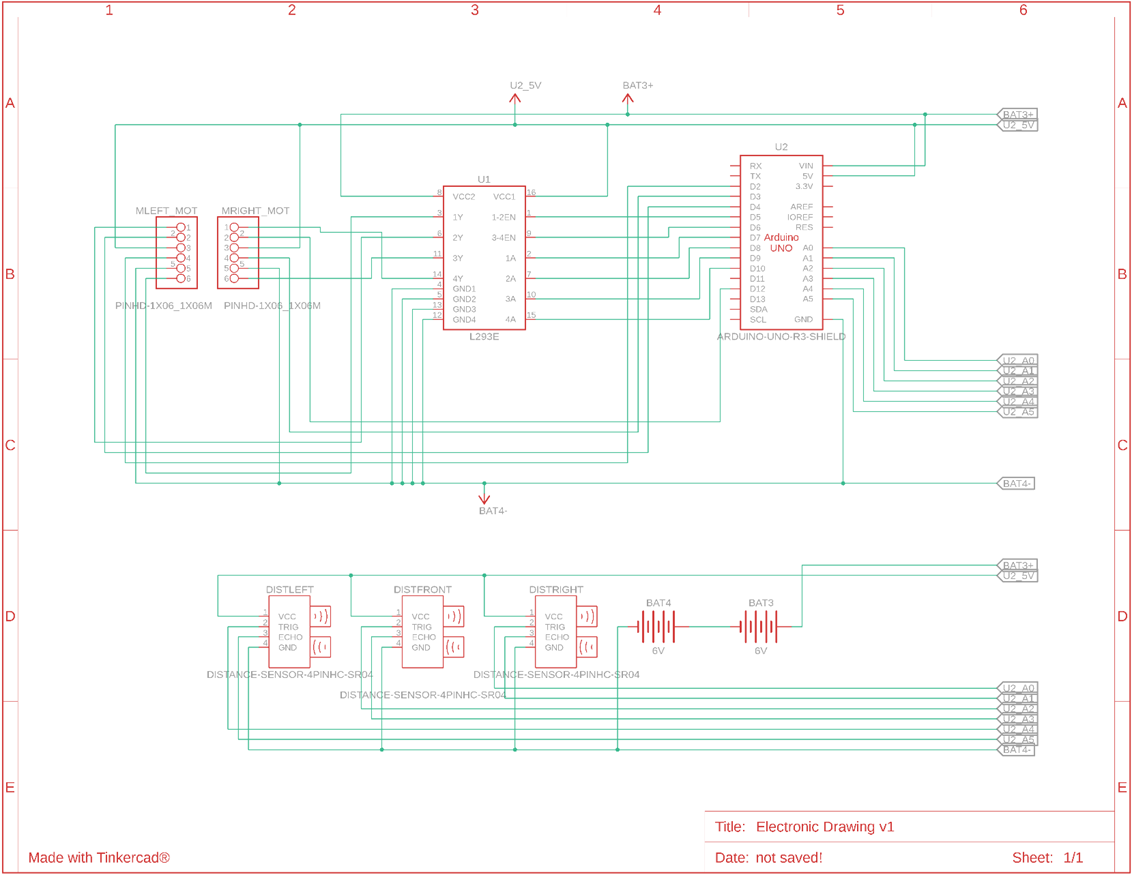
Tinkercad Diagram
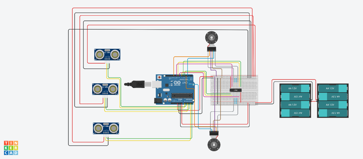
Connection Diagram
Arduino Code
Code Working
The code takes an area input from the serial monitor and upon entering starts a 5 second delay (can be calibrated) which allows the user to disconnect the USB cable and place the robot on the starting position.
The robot then systematically covers the entire area in rows while avoiding obstacles actively.
The robot also has a progress timeout, i.e. if it detects no significant movement for 60 seconds it will halt the motors
Code Adjustments
- WHEEL_DIAMETER (m), WHEEL_CIRCUMFERENCE (m), ROB_WIDTH (cm)
- COUNTS_PER_REVOLUTION (encoder pulse per revolution * gear ratio) , COUNTS_PER_METER (calibrate for 1 meter of movement)
- TURN_TIME (in milliseconds), calibrate till robot turns 90 degrees
- Ultrasonic Thresholds, OBSTACLE_DIST (cm) – distance at which robot will start avoiding obstacles and MAX_DIST (cm) – maximum sensor reading distance.
- PROGRESS_TIMEOUT is the time after which the robot will stop functioning if no motion is detected (in milliseconds)
- delay(5000), the time in milliseconds after inputting area in serial before the robot starts motion
Code
Adjustable parameters mentioned above are left blank with _$_ symbol
Component Drawings and Dimensions
Skills Required:
- CAD Design
- Drilling
- PCB design
- 3D Printing FDM
- Manual Soldering
- Laser Cutting
- Electronic Testing
- Arduino Programming
- Machining on Lathe
- Fabrication
- Milling on VMC