3D Printing FDM
Duration: 1 hr
Max CMF Points Earned: 200
Facility to Book: 3D Printers in CNC & 3D Printing Lab
Basic introduction to 3D printers:
First, one has to design the product using CAD software. Then, we can use slicing software to convert the CAD model into layers that a 3D printer can understand. Let's start by learning how to perform slicing.
Slicing
3D printer slicing is the process of converting a 3D CAD model (usually in STL, OBJ, or 3MF format) into instructions a 3D printer can understand — specifically, G-code. The G-code tells the printer how to move, extrude filament, and build the object layer by layer.
There are many open source slicing software available, but companies prefer their own slicing software to optimise for their 3D printer. Our lab consists Raise 3D and Creality company printers. Download the slicing software depending on which 3D printer that you want to use( Raise 3D, Creality).
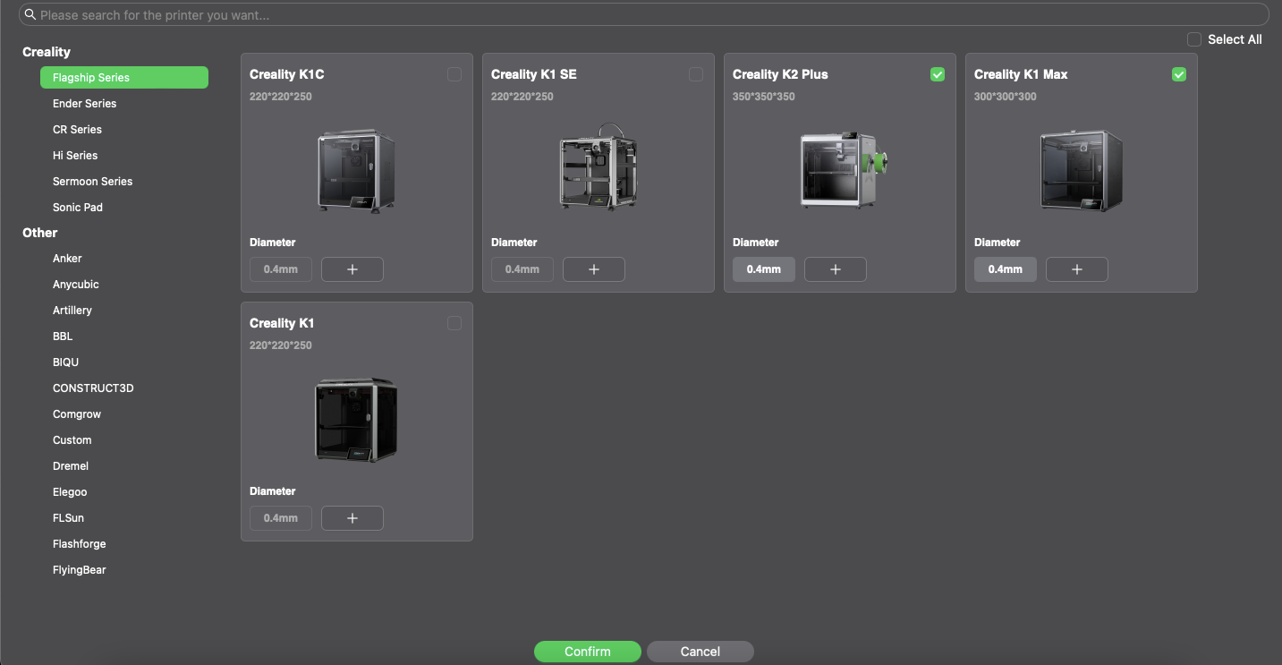
Step-1:
After downloading the slicer software add the 3D printer models available, for example choose Creality k1 max and Creality k2 Plus for creality.
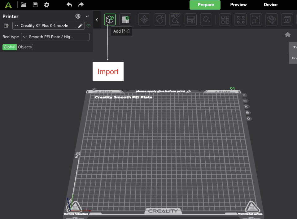
Step-2:
Import the CAD model in .stl format into the slicer
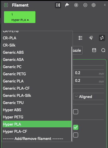
Step-3:
Choose the material, for example choose Hyper PLA
Step-4:
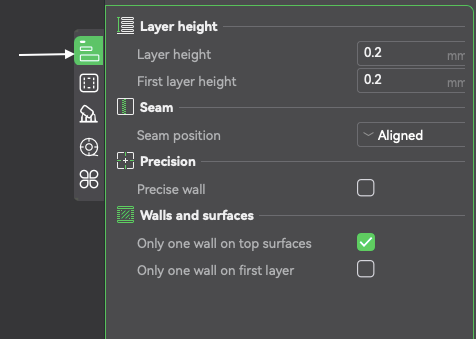
- On the right side, select the Quality option
- Select layer height 0.1 to 0.3
- Select the first layer height as default 0.2
- Choose the seam position aligned
- Select “only one wall on top surfaces”
Step-5:
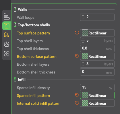
- Select the Strength option
- Set wall loops to 2
- Select top surface pattern as Rectilinear
- Set top shell layers to 5
- Set top shell thickness to 0.8 mm
- Select bottom surface pattern as Rectilinear
- Set bottom shell layers to 3
- Set bottom shell thickness to 0.3 mm
- Set sparse infill density to 15%
- Choose sparse infill pattern as Rectilinear
- Set internal solid infill pattern to Rectilinear
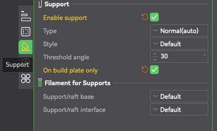
Step-6:
- Check "Enable support"
- Set support type to Normal (auto)
- Select support style as Default
- Set threshold angle to 30° (more conservative) to 45° (supports are generated for overhangs steeper than 45°)
- Leave "On build plate only" unchecked unless support from the plate is strictly required
- Use Default for both:
- Support/raft base
- Support/raft interface
| Feature | Skirt | Brim | Raft |
|---|---|---|---|
| Touches model? | No | Yes | Fully under |
| Improves adhesion? | No | Moderate | Maximum |
| Easy to remove? | Easy | Easy | Can be difficult |
| Use when? | Always (default) | Corners lifting | Warping, ABS, rough bed |
Step-7:
You can choose Auto to give you the position and orientation of the printing product.
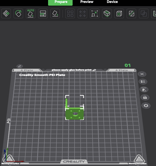
You have to use minimum material, so it is suggested to use minimum support material based on which part of the product needs fine finish you can change the orientation and location the printing part, it also helps in reducing printing time.
Step-8:
- In the other option, select Brim ―> choose Outer Brim
- Click on “Slice Plate” to prepare the model for printing
- Click on “Send to Print” to transfer the sliced file to the printer and choose export plate sliced file.

- Save the file to a USB pendrive in .gcode format for printer compatibility
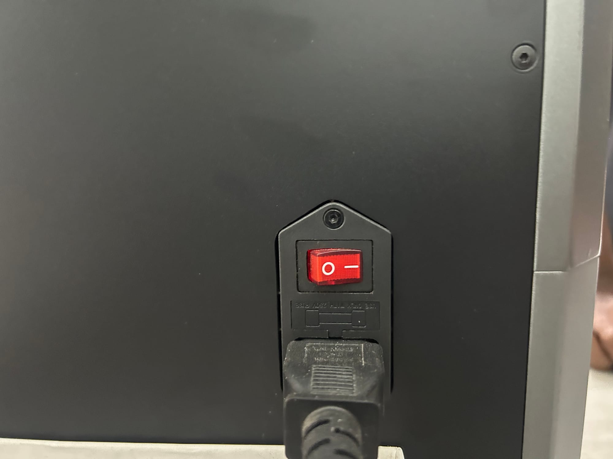
3D Printer Operation:
Step-1: There is switch at the back side of the printer. Make sure the printer is turned on.
Step-2: Insert the USB pendrive into the 3D printer’s USB port.
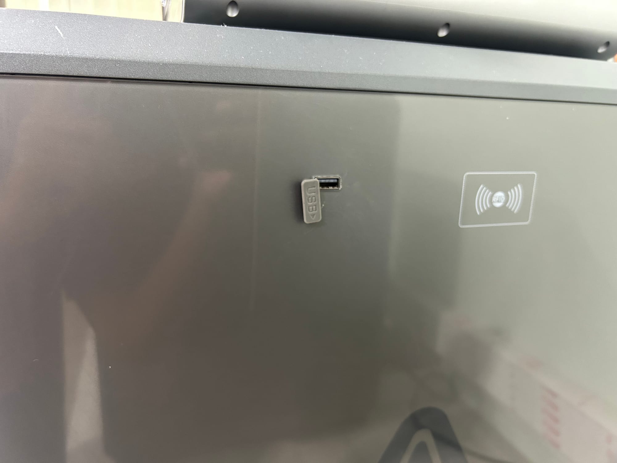
You can also directly connect to the printer wifi network and upload the files.
Step-3: Goto Folder―>USB file
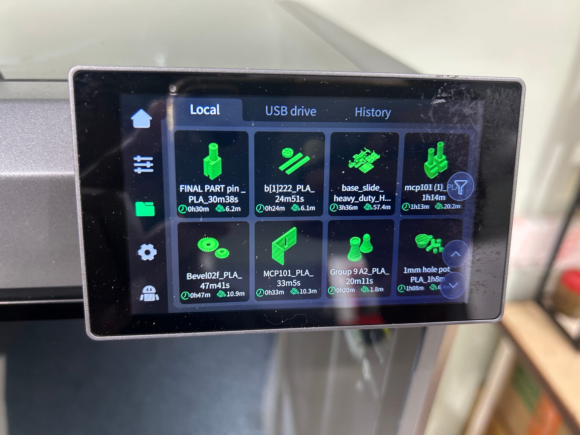
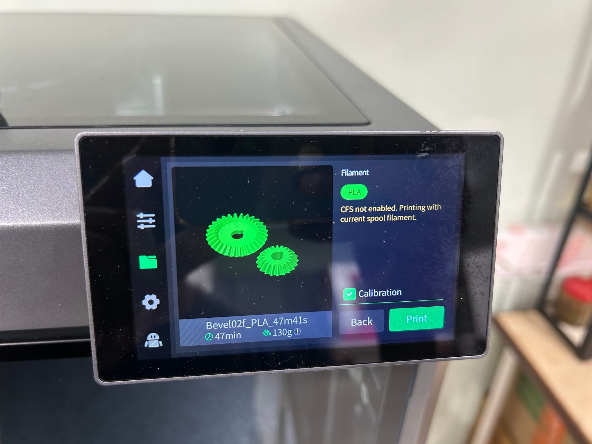
Select the desired part file on the printer screen and click “Print” to start the job
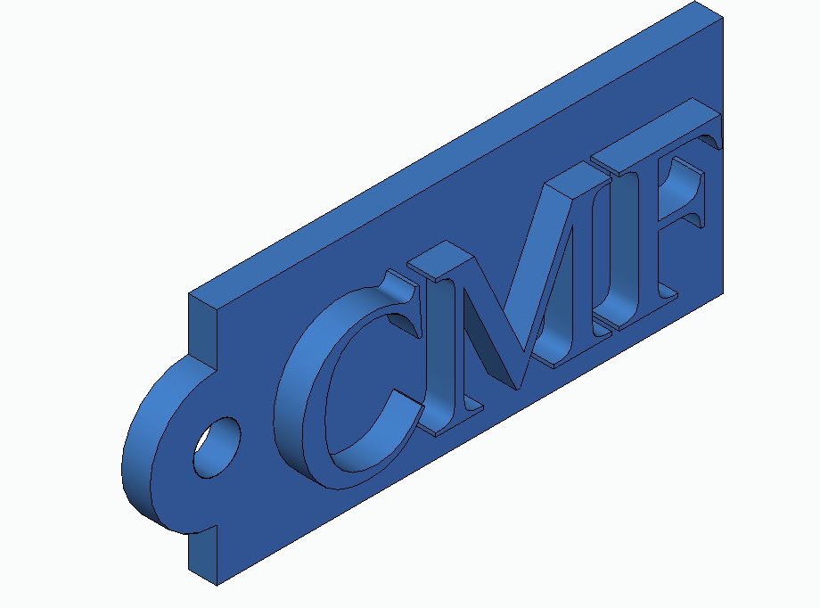
Task: Print a given CAD model
The CAD model of the product must be prepared by the student before booking the slot. The students must write their name in place of CMF.
Key chain
STL File to Print
Learning Outcomes:
- Learn how to make and print a 3D-designed model using a 3D printer.
- Slice models with appropriate print settings using Creality software
- Set up and operate an FDM 3D printer safely and effectively.
- Evaluate print quality and apply post-processing techniques for final part finishing.